Concept explainers
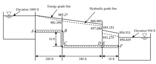
The drawing of the hydraulic gradient line and the energy grade line of the given system.
Explanation of Solution
Given:
Formula used:
Calculation:
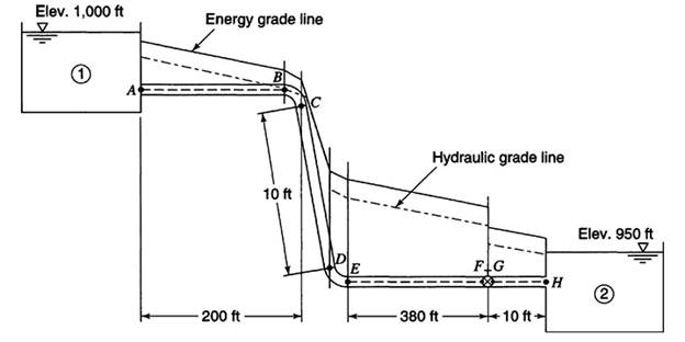
The given figure is shown below:
The flow between reservoir 1 and reservoir 2 is given by
The head loss is given by
The total minor head loss is given by
The relative roughness of pipe is given by
The value of the friction factor is 0.0165 from Moody’s diagram.
Now, substituting the value of the friction factor in the equation (1)
The discharge is given by
The velocity head is given by
The total head loss in the flow from A to B is given by
The hydraulic gradient line at B is given by
The energy gradient line at B is given by
Keep the hydraulic gradient line at point C the same as the hydraulic gradient line at point B.
The hydraulic gradient line at point C is given by
The energy gradient line at C is given by
The hydraulic gradient line at D is given by
The energy gradient line at D is given by
The hydraulic gradient line at E is given by
The energy gradient line at E is given by
The hydraulic gradient line at F is given by
The energy gradient line at F is given by
Want to see more full solutions like this?


- (b) A horizontal pipe is diverted upwards with an angle of 25 degrees. Water enters with a velocity of 4.5 ms-1 and exits upwards. The pipe entrance has a diameter of 200 mm and increases two times at the outlet. The inlet gauge pressure reads 80 kPa. If the difference vertical distance between inlet and outlet is 0.4 m, calculate the magnitude and direction of the resultant force on the pipe bend. Neglect energy losses and take the volume of water to be 0.18 m3arrow_forwardWater flows through a vertical contraction (venturi) section. Piezometers are attached to the upstream pipe and minimum area section as shown. The velocity in the pipe is 3 m/s. The difference in elevation between the two water levels in the piezometers is 15 cm. What is the velocity at the minimum area?arrow_forwardWater flows at a depth of y1=0.4ft in a concrete channel which is 10ft wide. The discharge per unit width is 10ft2/sec. Estimate the height of the hydraulic jump that will be formed if bed slope is equal to 0.0 and 0.15 respectively.arrow_forward
- Two reservoirs are connected by a pipeline consisting of pipe 1, pipe 2, pipe 3connected in series with length of 170 m, 300 m, 210 m respectively. Thedifferent in water surface levels in two reservoirs is 12 m. The friction coefficientfor pipe 1, pipe 2 and pipe 3 are 0.0052, 0.005 and 0.0048 respectively. Based onTable 2 and the setting given, determine the flowrate of the flow if the entranceloss coefficient is 0.25 considering :(i) minor losses; and(ii) neglecting minor losses pipe 1 =230(mm) Pipe 2 =330(mm) Pipe 3 = 430(mm)arrow_forwardIf the water surface elevation in reservoir B is 110 m, what must be the water surface elevation in reservoir A if a flow of 0.03 m3s is to occur in the cast-iron pipe? Use f = 0.021 for all pipes. Draw the HGL and the EGL, including changes in slope due to head loss. Neglect minor losses.arrow_forward1. The figure shows a looping water pipe system. Pressure at A = 85 m and E = 55m. Assume f = 0.053 all pipes. a. Compute the discharge at pipe 1b. Compute the discharge at pipe 2c. Compute the discharge at point Barrow_forward
- Try making the flow net for the following diagram. Given: H1= 6m H2= 1.5 m D= 8m D1= 4m Draw a flow netarrow_forwardShow complete solution(need ASAP): A flow net has been drawn as shown in the figure. Points A and C are at elevation ℎ1 and ℎ2 respectively above the datum. ? = 4 m ℎ1 = 4.7 m ℎ2 = 1.4 m Determine : a. Compute the piezometric pressure at point A in kPa. b. Compute the piezometric pressure at point C in kPa. c. Compute the piezometric head at point B in meters.arrow_forwardIn the pipeline shown in the figure, the diameter of all pipes (D) is 200 mm and their friction coefficient (f) is 0.02. Thisfor pipeline a) Calculate the maximum flow and draw the hydraulic slope plot. b) Flow rate Q=0.05 m3 To reduce to /s, calculate the required head loss on the valve and calculate the hydraulic slope line.draw. c) HP = 15 – 2000Q2 (Q:m3 /s, Hp: m) placement of a pump with characteristic equation at point BCalculate the flow rate and draw the hydraulic gradient line. Note: The criteria for 3 m < P/γ < 80 m and 0.5 m/s < V < 2 m/s along the pipeline must be met for all cases.arrow_forward
- Show the necessary figures (if applicable) 2.3) Points A and B are separated by 915 m of new 152.4 mm diameter cast iron pipe. 50 lps of water flow from point A to point B. Point B is 18.5 m above point A. What must be the pressure at point A if the pressure at point B is 345 kPag and the head loss between A and B is 54 m? 2.4) A pipe discharges 142 lps of water into a reservoir at a point 1.85 m below the water surface. At point A the diameter is 25.4 cm and the center of the pipe is 1.25 m above the water surface. At the discharge end the pipe is 30.5 cm. If the head loss from A to the reservoir is 0.7 m, determine the pressure in A.arrow_forwardCompute the velocity of the flow for a very smooth pipe if the hydraulic radius is 10ft, and slope is 0.5 using Hazen-Williams Formula.arrow_forwardCompute the value of the hydraulic radius for a circular pipe flowing half-full.arrow_forward

 Structural Analysis (10th Edition)Civil EngineeringISBN:9780134610672Author:Russell C. HibbelerPublisher:PEARSON
 Principles of Foundation Engineering (MindTap Cou...Civil EngineeringISBN:9781337705028Author:Braja M. Das, Nagaratnam SivakuganPublisher:Cengage Learning
 Fundamentals of Structural AnalysisCivil EngineeringISBN:9780073398006Author:Kenneth M. Leet Emeritus, Chia-Ming Uang, Joel LanningPublisher:McGraw-Hill Education
 Traffic and Highway EngineeringCivil EngineeringISBN:9781305156241Author:Garber, Nicholas J.Publisher:Cengage Learning