
Videos
The link lengths and the value of

Trending nowThis is a popular solution!

Chapter 4 Solutions
DESIGN OF MACHINERY
Additional Engineering Textbook Solutions
HEAT+MASS TRANSFER:FUND.+APPL.
Fundamentals of Heat and Mass Transfer
Thinking Like an Engineer: An Active Learning Approach (3rd Edition)
Vector Mechanics for Engineers: Statics and Dynamics
Machine Tool Practices (10th Edition)
Thinking Like an Engineer: An Active Learning Approach (4th Edition)


- A general fourbar linkage configuration and its notation are shown in Figure below. The link lengths, coupler point location, and the values of 02 and w2 for the same fourbar linkages as used for position analysis in Chapter 4 are redefined in Table below. For the row c, draw the linkage to scale and Using an analytical method calculate w3 and w4 and find the velocity of point P. find the velocities of the pin joints A and. RPA Y B 4 03 04 02 1 02 FIGURE P6-1 Configuration and terminology for the pin-jointed fourbar linkage of Problems 6-4 to 6-5 TABLE P6-1 Data for Problems 6-4 to 6-5† Row Link 1 Link 2 Link 3 Link 4 02 Rpa 83 02 a 2 7 9. 30 10 30 7 9. 8 85 -12 9 25 3 10 8 45 -15 10 80arrow_forwardA general fourbar linkage configuration and its notation are shown in Figure below. The link lengths, coupler point location, and the values of 02 and w2 for the same fourbar linkages as used for position analysis in Chapter 4 are redefined in Table below. For the row c, draw the linkage to scale and Using an analytical method calculate w3 and w4 and find the velocity of point P. find the velocities of the pin joints A and. RPA AY 2 04 02 04 FIGURE P6-1 Configuration and terminology for the pin-Jointed fourbar linkage of Problems 6-4 to 6-5 TABLE P6-1 Data for Problems 6-4 to 6-5† Row Link 1 Link 2 Link 3 Link 4 02 02 Rpa 83 6. 2 7 30 10 6. 30 b. 9 3 8 85 -12 9. 25 10 6. 8 45 -15 10 80 O73arrow_forwardConsider the figure as shown below. O-XoYoZo is the reference frame and O-X₁Y₁Z₁ is the frame attached to the tool. Sketch the tool position after each intermediate position of the operation of the tool about the reference frame: roll π/2(rotate about Zo), pitch -T/2(rotate about Yo), yaw π/2(rotate about Xo). Please write the final rotation matrix expression. ZI,Zo XI,Xo Yı, Yoarrow_forward
- What is the equivalent root of the system of the figure using the displacement of the block as a generalized coordinatearrow_forwardSlide B travels along the center line XX'. Q2A = 18 cm, AB = 72 cm. 1. With the crank in the position shown, draw the four bar linkage. Name each link and show the finite and infinite cranks.2. Find the two extreme positions of block B. Express your answer in terms of the acute angle formed by crank Q2A with the horizontal axis (like the angle 45° in the figure)3. Determine the length of the stroke of B. Write your answer in two decimal places.arrow_forwardFigure out the 2D sketch of housing using AutoCAD and mention all the dimensions. Colour the hatched lines which are inside the curve (red) 37 30 14 R 2 holes 72 Dia 12R 60R 30 R 24 10 R 15R Housing 60 Rarrow_forward
- The general linkage configuration and terminology for an offset fourbar slider- crank linkage are shown in the figure. The link lengths and the values of d, d.d and d..d are defined in the table. For row a, using graphical method, the value the acceleration of pin joint A is Row la b C d le If g 02 002 Link 2 1.4 2 3 3.5 5 3 0₂ Y Link 2 O 792.064 in/sec2 0₂ 291.385 in/sec2 O 1,593 in/sec2 O 1,779 in/sec2 Link 3 14 16 18 10 20 13 25 Link 3 Offset 1 -3 2 1 -5 10 10 Offset 03 Slider position d, d, d d 2.5 5 8 -8 15 -12 25 y B d.d d..d 10 -12 15 -15 -10 24 -4 -50 10 -45 50 100 18 04 = 90° 10 Xarrow_forwardProblem 4.7 ( example on analytical position analysis of pinjointed fourbar linkage) The link lengths and the value of 0, for some fourbar linkages are defined in Table P4-1. 1. For row a, find all possible solutions (both open and crossed) for angles 0, and 0, using the vector loop method. R3 R4 R2 R1 04 FIGURE 4-6arrow_forwardConsider that we have a 3-R robot as shown in the figure below. The lengths of the links are: 11-12-13=2. The position and posture of the tool's center point is Pt (x₁, y₁, α), the driving variables are 01, 02, 03, and the output variables are v,v,, w.. (It is in the initial position) yo 1₁ Y₁ 0₁ Y₂ 12 02 X1 -X2 V3 13 P₁ X3 a Xoarrow_forward
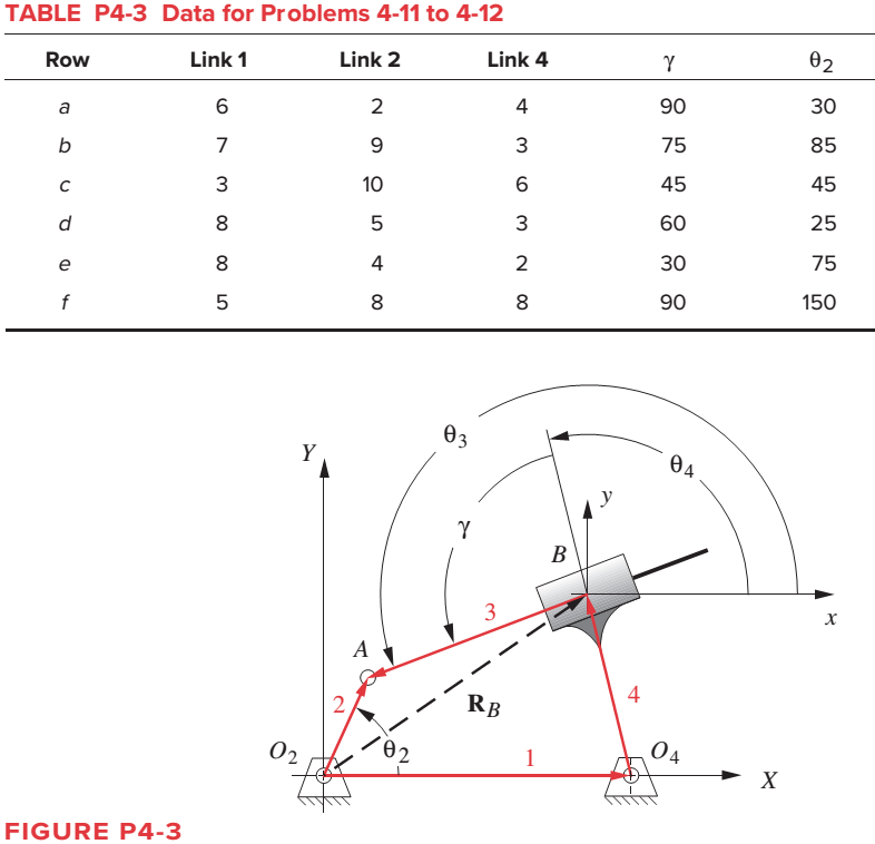
- The following shows the top view of the partially open doors on one side of an entertainment center cabinet. The wooden doors are hinged to each other and one door is hinged to the cabinet. There is also a ternary, metal link attached to the cabinet and door through pin joints. As spring- loaded piston-in-cylinder device attaches to the ternary link and the cabinet through pin joints. Draw a kinematic diagram of the door system and find the mobility of this mechanism. cylinder piston O cabinet link hinge door door hingearrow_forwardFor the walking-beam mechanism of Figure P4-9, calculate and plot the xand y components of the position of the coupler point P for one complete revolution of the crank O2A. Hint: Calculate them first with respect to the ground link O204 and then transform them into the global XY coordinate system (i.e., horizontal and vertical in the figure). Scale the figure for any additional information neededarrow_forwardA general inverted fourbar slider-crank linkage has links length: link 2 = a = 2, link 4 = c = 4, and link 1= d = 6 in. The input values are 02 = 60°, y = 90°. The linkage configuration and terminology are shown in figure below; note that this figure does not represent the real dimensions of the linkage We need to find the angular positions of link 4 (04), of link 3 (03) and the effective length of link 3 (b) for both open and crossed configurations. 03 Өд В 4 RB 02 02 1 02 04 Choose... For open configuration, the angle 04 measured form X axis CCW in degree = Choose... For open configuration, the angle 03 measured form X axis CCW in degree = Choose... + For open configuration, the absolute value of the effective length of link 3, b = Choose... For crossed configuration, the angle 04 measured form X axis CCW in degree = Choose... For crossed configuration, the angle 03 measured form X axis CCW in degree = Choose... For crossed configuration, the absolute value of the effective length of…arrow_forward
 Elements Of ElectromagneticsMechanical EngineeringISBN:9780190698614Author:Sadiku, Matthew N. O.Publisher:Oxford University Press
 Mechanics of Materials (10th Edition)Mechanical EngineeringISBN:9780134319650Author:Russell C. HibbelerPublisher:PEARSON
 Thermodynamics: An Engineering ApproachMechanical EngineeringISBN:9781259822674Author:Yunus A. Cengel Dr., Michael A. BolesPublisher:McGraw-Hill Education
 Control Systems EngineeringMechanical EngineeringISBN:9781118170519Author:Norman S. NisePublisher:WILEY
 Mechanics of Materials (MindTap Course List)Mechanical EngineeringISBN:9781337093347Author:Barry J. Goodno, James M. GerePublisher:Cengage Learning
 Engineering Mechanics: StaticsMechanical EngineeringISBN:9781118807330Author:James L. Meriam, L. G. Kraige, J. N. BoltonPublisher:WILEY