
Concept explainers
Videos
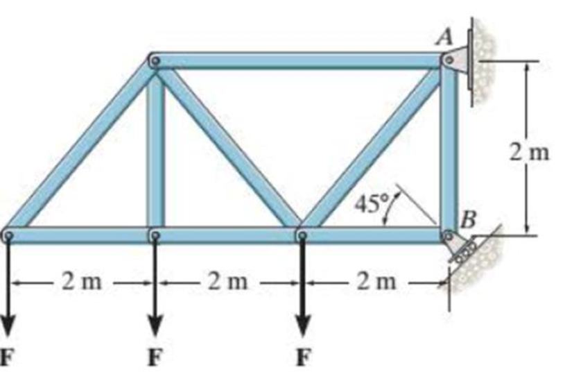
If the roller at B can sustain a maximum load of 3 kN, determine the largest magnitude of each of the three forces F that can be supported by the truss.
Prob. R4-1
Find the largest magnitude of each of the three forces F that can be supported by the truss.
Answer to Problem 1RP
The largest magnitude of each of the three forces F that can be supported by the truss is
Explanation of Solution
Given information:
- The maximum load (P) of a roller support is 3 kN.
- The length (L) between support A and B is 2 meters.
- Intensity of load is F and the load is acting at a distance of 2 m, 4 m, and 6 m respectively from support A.
Calculation:
Show the free body diagram of the truss as in Figure 1.
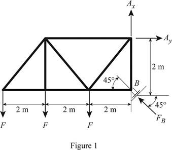
Use Figure 1.
Determine the largest magnitude of each of the three forces F that can be supported by the truss by taking the moment about support A.
Here, the distance of force F acting on a truss at various points is
Show the calculation of force as follows:
Conclusion:
Substitute 6.0 m for
Thus, the largest magnitude of each of the three forces F that can be supported by the truss is
Want to see more full solutions like this?
Chapter 4 Solutions
Statics and Mechanics of Materials Plus Mastering Engineering with Pearson eText - Access Card Package (5th Edition)
Additional Engineering Textbook Solutions
Thinking Like an Engineer: An Active Learning Approach (4th Edition)
Manufacturing Engineering & Technology
Machine Elements in Mechanical Design (6th Edition) (What's New in Trades & Technology)
Engineering Mechanics: Statics & Dynamics (14th Edition)
Thermodynamics: An Engineering Approach
Fluid Mechanics Fundamentals And Applications


- 6-85. The three power lines exert the forces shown on the truss joints, which in turn are pin-connected to the poles AH and EG. Determine the force in the guy cable AI and the pin reaction at the support H. 20 ft D B -40 ft--40 ft- 800 lb 800 lb H 800 lb -50 ft-30 ft--30 20 ft -30 ft-30 ft-30 ft-30 ft 30 ft-30 20 ft ft-50 ft- 125 ftarrow_forward3-19. Determine the force in members AE, BE, and BC of the truss and indicate if the members are in tension or compression 8 k A 12 k 6 k 8 ft. E 00 00 00 0.0.0.0. B Prob. 3-19 8 ft D 00 00 ° 0 00 6 ft Carrow_forwardDetermine the resultant force at pins A, B, and C on the three-member frame. Given: F = 40N, w = 10, L = 1.arrow_forward
- 6-50. Determine the force in each member of the truss and state if the members are in tension or compression. Set P = 20 kN, P, = 10 kN. Determine the force in each member of the truss and state if the members are in tension or compression. Set P, = 40 kN, P2 = 20 kN. B C D 2 m E A |F -1.5 m--1.5 m--1.5 m-|-1.5 m-| |G P2 Probs. 6–50/51 Answers: FA = 21.875 = 21.9 kN (C) ; Fag = 13.125 = 13.1 kN (T)arrow_forward3-10. Determine the force in each member of the truss. State if the members are in tension or compression. 4 m 15 kN 3m B 20 kN E 2m +2m+ 10 kN 3marrow_forward4 of 8 5-27. As an airplane's brakes are applied, the nose wheel exerts two forces on the end of the landing gear as shown. Determine the horizontal and vertical components of reaction at the pin C and the force in strut AB. B. 30 400 mm 20° 600 mm 2 kN 6 kNarrow_forward
- P5-3. then draw the free-body diagrams of each member of the identify any two-force members, and frame. 2 m 400 N в 0.2 m 1.5 marrow_forward6-127. Determine the clamping force exerted on the smooth pipe at B if a force of 20 lb is applied to the handles of the pliers. The pliers are pinned together at A. 20 lb 20 lb 10 in. 40° 1.5 in. 0.5 in. Barrow_forward*6-76. Determine the horizontal and vertical components of force which the pins at A, B, and C exert on member ABC of the frame. 400 N -1.5 m- -2 m- 1.5 m 2.5 m – 300 N -B 2 m – 300 N 2.5 m 1.5 m Earrow_forward
- 6-34. Determine the force in members JK, CJ, and CD of the truss, and state if the members are in tension or compression. Determine the force in members HI, FI, and EF of the truss, and state if the members are in tension or compression. K 3 m Is G E F |-2 m--2 m--2 m-|-2 m--2 m--2 m-| B |C |D 4 kN 5 kN 8 kN 6 kN Probs. 6-34/35 Answers FK =11.111KN = 11.1 kN (C) FCD = 12 kN (T) Fc =1.602 kN = 1.60 kN (C)arrow_forward*3-12. The concrete pipe elbow has a weight of 400 lb and the center of gravity is located at point G. Determine the force FAR and the tension in cables BC and BD needed to support it. FAB B 30 in, 45° 45° 30 in. D Garrow_forward*3-4. Cords AB and AC can each sustain a maximum tension of 800 lb. If the drum has a weight of 900 lb, determine the smallest angle 0 at which they can be attached to the drum. B. 10arrow_forward
 Elements Of ElectromagneticsMechanical EngineeringISBN:9780190698614Author:Sadiku, Matthew N. O.Publisher:Oxford University Press
 Mechanics of Materials (10th Edition)Mechanical EngineeringISBN:9780134319650Author:Russell C. HibbelerPublisher:PEARSON
 Thermodynamics: An Engineering ApproachMechanical EngineeringISBN:9781259822674Author:Yunus A. Cengel Dr., Michael A. BolesPublisher:McGraw-Hill Education
 Control Systems EngineeringMechanical EngineeringISBN:9781118170519Author:Norman S. NisePublisher:WILEY
 Mechanics of Materials (MindTap Course List)Mechanical EngineeringISBN:9781337093347Author:Barry J. Goodno, James M. GerePublisher:Cengage Learning
 Engineering Mechanics: StaticsMechanical EngineeringISBN:9781118807330Author:James L. Meriam, L. G. Kraige, J. N. BoltonPublisher:WILEY