STRUCTURAL ANALYSIS (LL)
6th Edition
ISBN: 9780357030967
Author: KASSIMALI
Publisher: CENGAGE L
bartleby

Concept explainers

Question
Book Icon
Chapter 4, Problem 12P
To determine

Find the forces in the members of the truss by the method of joints.

Expert Solution & Answer
Check Mark

Answer to Problem 12P

The forces in the member are FIJ=FJH=0kN_, FHI=50kN(C)_, FGI=30kN(T)_, FGH=40kN(T)_, FFH=30kN(C)_, FFG=150kN(C)_, FEG=120kN(T)_, FEF=120kN(T)_, FDF=120kN(C)_, FDE=250kN(C)_, FCE=270kN(T)_, FCD=200kN(T)_, FBD=270kN(C)_, FBC=350kN(C)_, FAC=480kN(T)_, and FAB=280kN(T)_.

Explanation of Solution

Given information:

Apply the sign conventions for calculating reactions, forces and moments using the three equations of equilibrium as shown below.

  • For summation of forces along x-direction is equal to zero (Fx=0), consider the forces acting towards right side as positive (+) and the forces acting towards left side as negative ().
  • For summation of forces along y-direction is equal to zero (Fy=0), consider the upward force as positive (+) and the downward force as negative ().
  • For summation of moment about a point is equal to zero (Matapoint=0), consider the clockwise moment as negative and the counter clockwise moment as positive.

Method of joints:

The negative value of force in any member indicates compression (C) and the positive value of force in any member indicates Tension (T).

Calculation:

Consider the forces in the members AC, CE, EG, GI, IJ, BD, DF, FH, HJ, AB, BC, CD, DE, EF, FG, GH, and HI, are FAC,FCE,FEG,FGI,FIJ,FBD,FDF,FFH,FHJ,FAB,FBC,FCD,FDE,FEF,FFG,FGH,FHI.

Show the free body diagram of the truss as shown in Figure 1.
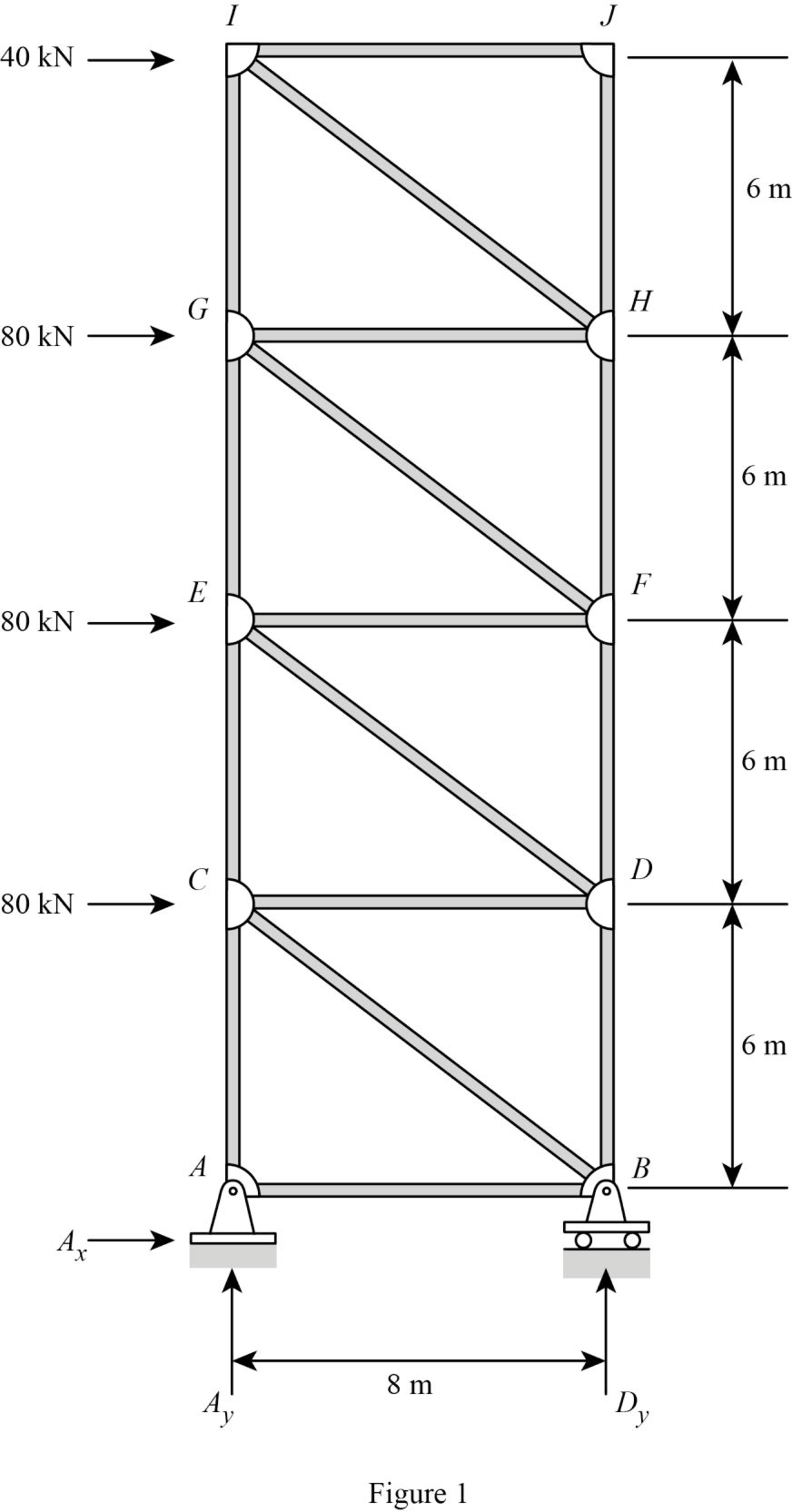
STRUCTURAL ANALYSIS (LL), Chapter 4, Problem 12P , additional homework tip  1

Refer Figure 1.

Consider the member BC, DE, FG, and HI with the horizontal as θ.

tanθ=68θ=tan1(68)θ=36.86°

Consider the horizontal and vertical reactions at A are Ax and Ay.

Consider the vertical reaction at B is By.

Take the sum of the forces in the vertical direction as zero.

Fy=0Ay+By=0Ay=By        (1)

Take the sum of the forces in the horizontal direction as zero.

Fx=0Ax+80+80+80+40=0Ax=280kN

Take the sum of the moments at A is zero.

MA=0(80×6)(80×12)(80×18)(40×24)+8By=03840+8By=0By=38408By=480kN

Substitute 480kN for By in Equation (1).

Ay=480kN

Show the joint A as shown in Figure 2.
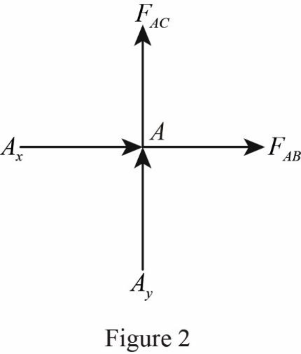
STRUCTURAL ANALYSIS (LL), Chapter 4, Problem 12P , additional homework tip  2

Refer Figure 2.

Take the sum of the forces in the horizontal direction as zero.

Fx=0Ax=FABFAB=(280kN)FAB=280kN(T)

Take the sum of the forces in the vertical direction as zero.

Fy=0Ay=FACFAC=(480kN)FAC=480kN(T)

Show the joint B as shown in Figure 3.
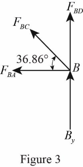
STRUCTURAL ANALYSIS (LL), Chapter 4, Problem 12P , additional homework tip  3

Refer Figure 3.

Take the sum of the forces in the horizontal direction as zero.

 Fx=0FBCcosθ=FBAFBC=FBAcos(36.86°)FBC=280cos(36.86°)FBC=350kN(C)

Take the sum of the forces in the vertical direction as zero.

Fy=0By+FBCsinθ=FBDBy+(350)sin(36.86°)=FBD

Substitute 480kN for By

480+(350)sin(36.86°)=FBD480+(350)sin(36.86°)=FBDFBD=270kNFBD=270kN(C)

Show the joint C as shown in Figure 4.

STRUCTURAL ANALYSIS (LL), Chapter 4, Problem 12P , additional homework tip  4

Refer Figure 4.

Take the sum of the forces in the horizontal direction as zero.

 Fx=080+FCBcos36.86°+FCD=080+(350)cos36.86°+FCD=0FCD=350cos36.86°80FCD=200kN(T)

Take the sum of the forces in the vertical direction as zero.

Fy=0FCEFCAFCBsin36.86°=0FCE(480)(350)sin36.86°=0FCE=270kN(T)

Show the joint D as shown in Figure 5.
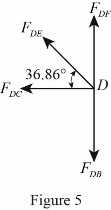
STRUCTURAL ANALYSIS (LL), Chapter 4, Problem 12P , additional homework tip  5

Refer Figure 5.

Take the sum of the forces in the horizontal direction as zero.

 Fx=0FDEcosθ=FDCFDE=200cos(36.86°)FDE=250kN(C)

Take the sum of the forces in the vertical direction as zero.

Fy=0FDB+FDEsinθ=FDF(270)+(250)sin(36.86°)=FDF120kN=FDFFDF=120kN(C)

Show the joint E as shown in Figure 6.
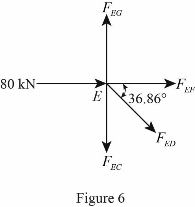
STRUCTURAL ANALYSIS (LL), Chapter 4, Problem 12P , additional homework tip  6

Refer Figure 6.

Take the sum of the forces in the horizontal direction as zero.

 Fx=080+FEDcos36.86°+FEF=080+(250)cos36.86°+FEF=0FEF=250cos36.86°80FEF=120kN(T)

Take the sum of the forces in the vertical direction as zero.

Fy=0FEGFECFEDsin36.86°=0FEG(270)(250)sin36.86°=0FEG=120kNFEG=120kN(T)

Show the joint F as shown in Figure 7.
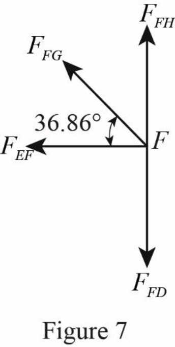
STRUCTURAL ANALYSIS (LL), Chapter 4, Problem 12P , additional homework tip  7

Refer Figure 7.

Take the sum of the forces in the horizontal direction as zero.

 Fx=0FFGcosθ=FEFFFG=120cos(36.86°)FFG=150kN(C)

Take the sum of the forces in the vertical direction as zero.

Fy=0FFD+FFGsinθ=FFH(120)+(150)sin(36.86°)=FFH30kN=FFHFFH=30kN(C)

Show the joint G as shown in Figure 8.
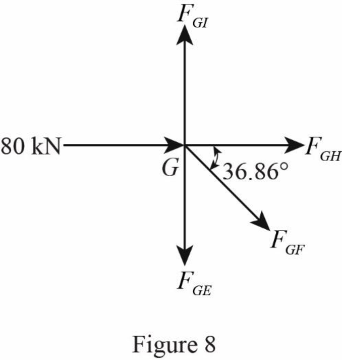
STRUCTURAL ANALYSIS (LL), Chapter 4, Problem 12P , additional homework tip  8

Refer Figure 8.

Take the sum of the forces in the horizontal direction as zero.

 Fx=080+FGFcos36.86°+FGH=080+(150)cos36.86°+FGH=0FGH=150cos36.86°80FGH=40kN(T)

Take the sum of the forces in the vertical direction as zero.

Fy=0FGIFGEFGFsin36.86°=0FGI(120)(150)sin36.86°=0FGI=30kNFGI=30kN(T)

Show the joint H as shown in Figure 9.
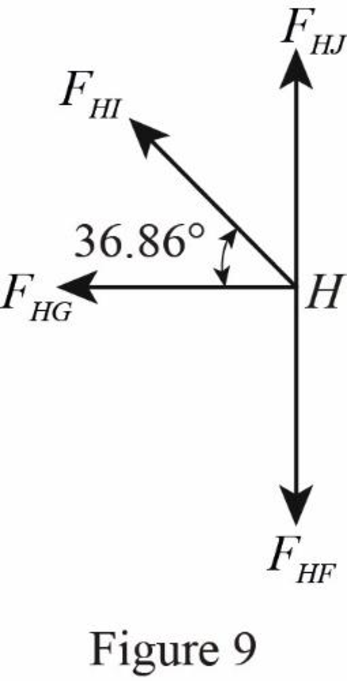
STRUCTURAL ANALYSIS (LL), Chapter 4, Problem 12P , additional homework tip  9

Refer Figure 9.

Take the sum of the forces in the horizontal direction as zero.

 Fx=0FHIcosθ=FHGFHI=40cos(36.86°)FHI=50kN(C)

The forces in the member IJ and JH is zero as no force is acts at the joint J.

Thus, the forces in the member are FIJ=FJH=0kN_, FHI=50kN(C)_, FGI=30kN(T)_, FGH=40kN(T)_, FFH=30kN(C)_, FFG=150kN(C)_, FEG=120kN(T)_, FEF=120kN(T)_, FDF=120kN(C)_, FDE=250kN(C)_, FCE=270kN(T)_, FCD=200kN(T)_, FBD=270kN(C)_, FBC=350kN(C)_, FAC=480kN(T)_, and FAB=280kN(T)_.

Want to see more full solutions like this?

Subscribe now to access step-by-step solutions to millions of textbook problems written by subject matter experts!
Students have asked these similar questions
Section 4.5 4.6 through 4.28 Determine the force in each member of the truss shown by the method of joints. T 5 ft Į FIG. P4.13 D A -12 ft 12 5 6.5 k B 20 k 12 ft E 12 ft 10 k
Determine the force in members AB, BD, CD and DF of the truss shown in Fig. P-414
Determine the force in each member of the compound truss shown in Fig. 4.25(a)
Knowledge Booster
Background pattern image
Civil Engineering
Learn more about
Need a deep-dive on the concept behind this application? Look no further. Learn more about this topic, civil-engineering and related others by exploring similar questions and additional content below.
Recommended textbooks for you
  • Text book image
    Structural Analysis
    Civil Engineering
    ISBN:9781337630931
    Author:KASSIMALI, Aslam.
    Publisher:Cengage,
Text book image
Structural Analysis
Civil Engineering
ISBN:9781337630931
Author:KASSIMALI, Aslam.
Publisher:Cengage,