
Videos
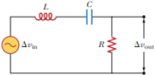
The resistor in Figure P32.49 represents the midrange speaker in a three-speaker system. Assume its resistance to be constant at 8.00 Ω. The source represents an audio amplifier producing signals of uniform amplitude ΔVmax = 10.0 V at all audio frequencies. The inductor and capacitor are to function as a band-pass filter with
Figure P32.49
(a)
Answer to Problem 49CP
Explanation of Solution
Given info: The value of resistance is
Formula to calculate the output potential difference is,
Here,
Formula to calculate the input potential difference is,
Here,
Divide equation (1) and equation (1).
Formula to calculate the inductive reactance of the circuit is,
Here,
Formula to calculate the inductive reactance of the circuit is,
Here,
Formula to calculate the impedance of the circuit is,
Here,
Substitute
At low frequency that is
Substitute
Substitute
Solve the equation further,
Divide the equation by
At high frequency that is
Substitute
Substitute
Solve the equation further,
Subtract the equation (5) and equation (6) to find the value of
Conclusion:
Therefore, the required value of inductance
(b)
Answer to Problem 49CP
Explanation of Solution
Given info: The value of resistance is
The equation (6) is given as,
Substitute
Conclusion:
Therefore, the required value of capacitance
(c)
Answer to Problem 49CP
Explanation of Solution
Given info: The value of resistance is
The value
At resonance condition,
Substitute
Conclusion:
Therefore, the maximum value of the ratio
(d)
Answer to Problem 49CP
Explanation of Solution
Given info: The value of resistance is
Since the ratio
Formula to calculate the resonance frequency is,
Substitute
Conclusion:
Therefore, the frequency
(e)
Answer to Problem 49CP
Explanation of Solution
Given info: The value of resistance is
Formula to calculate the phase shift between
At
Substitute
At
Substitute
At
Substitute
Conclusion:
Therefore, the phase shift between
(f)
Answer to Problem 49CP
Explanation of Solution
Given info: The value of resistance is
Formula to calculate the rms output voltage is,
Formula to calculate the power deliver to the speaker is,
Substitute
For low frequency
Substitute
Substitute
For resonance frequency
Substitute
Substitute
Conclusion:
Therefore, the average power transferred to the speaker at
(g)
Answer to Problem 49CP
Explanation of Solution
Given info: The value of resistance is
Formula to calculate the quality factor is,
Substitute
Conclusion:
Therefore, the quality factor of the circuit is
Want to see more full solutions like this?
Chapter 32 Solutions
EBK PHYSICS FOR SCIENTISTS AND ENGINEER


- An PLC series circuit with R=600 , L = 30 mH. and c=0.050F is driven by an ac source whose frequency and voltage amplitude are 500 Hz and 50 V, respectively, (a) What is the impedance of the circuit? (b) What is the amplitude of the current in the circuit? (c) What is the phase angle between the emf of the source and the current?arrow_forwardAn ac source of voltage amplitude 100 V and frequency 1.0 kHz drives an PLC series circuit with R=20, L = 4.0 mH, and C=50F . (a) Determine the rms current through the circuit, (b) What are the rms voltages across the three elements? (c) What is the phase angle between the emf and the current? (d) What is the power output of the source? (e) What is the power dissipated in the resistor?arrow_forwardAn AC source of angular frequency is connected to a resistor R and a capacitor C in series. The maximum current measured is Imax. While the same maximum emf is maintained, the angular frequency is changed to /3. The measured current is now I/2. Determine the ratio of the capacitive reactance to the resistance at the initial frequency .arrow_forward
- In a purely inductive AC circuit as shown in Figure P32.6, Vmax = 100 V. (a) The maximum current is 7.50 A at 50.0 Hz. Calculate the inductance L. (b) What If? At what angular frequency is the maximum current 2.50 A? Figure P32.6 Problem 6 and 7.arrow_forwardIn an RLC series circuit, the voltage amplitude and frequency of the source are 100 V and 500 Hz, respectively, an R = 5O0. L=0.20H, and C=2.0F . (a)What is the impedance of the circuit? (b) What is the amplitude of the current from the source? (C) If the emf of the source Is given by v(tt)=(100V)sin , how does the current vary with time? (d) Repeat the calculations with C changed to 0.20F .arrow_forwardIn a purely inductive AC circuit as shown in Figure P21.15, Vmax = 100. V. (a) The maximum current is 7.50 A at 50.0 Hz. Calculate the inductance L. (b) At what angular frequency is the maximum current 2.50A? Figure p21.15arrow_forward
- An AC source with Vmax = 150 V and f = 50.0 Hz is connected between points a and d in Figure P32.16. Calculate the maximum voltages between (a) points a and b, (b) points b and c, (c) points c and d, and (d) points b and d. Figure P32.16 Problems 16 and 51.arrow_forwardA series RLC circuit has resistance R = 50.0 and inductance L. = 0.500 H. (a) Find the circuits capacitance C if the voltage source operates at a frequency of f = 60.0 Hz and the impedance is Z = R = 50.0 . (b) What is the phase angle between the current and the voltage?arrow_forwardAn 19.0-µF capacitor is connected across an AC source with Vmax = 80.0 V oscillating at 45.0 Hz. What is the maximum current in the capacitor?arrow_forward
- Nowadays, touch screen devices are everywhere. Consider a simple capacitive touch sensor comprised of a resistor with resistance R=1.57 MΩ and a capacitor with capacitance C=1.09 nF connected in series. A standard wall outlet powers the sensor with an output frequency f=50.0 Hz. Pressing the sensor triples the capacitance of the circuit. A logic gate detects a change in the circuit's impedance. Determine the initial impedance Z0 of the circuit in megaohms (MΩ). Determine the impedance Zp of the circuit with a pressed sensor in megaohms (MΩ).arrow_forwardRefer to the figure to the right, 185 mH 65.0 uF 40.0 0 if an AC source of frequency @=50 Hz is connected to the points a and d. What is the capacitive reactance in this circuit? Figure P32.16 Problems 16 and 51.arrow_forwardA 250 Ω resistor is connected in series with a 4.80 mF capacitor and an ac source. The voltage across the capacitor is vC = (7.60 V)sin[(120 rad/s)t]. (a) Determine the capacitive reactance of the capacitor. (b) Derive an expression for the voltage vR across the resistorarrow_forward
 Physics for Scientists and EngineersPhysicsISBN:9781337553278Author:Raymond A. Serway, John W. JewettPublisher:Cengage Learning
 Physics for Scientists and Engineers with Modern ...PhysicsISBN:9781337553292Author:Raymond A. Serway, John W. JewettPublisher:Cengage Learning
 Physics for Scientists and Engineers: Foundations...PhysicsISBN:9781133939146Author:Katz, Debora M.Publisher:Cengage Learning
 College PhysicsPhysicsISBN:9781305952300Author:Raymond A. Serway, Chris VuillePublisher:Cengage Learning
 Physics for Scientists and Engineers, Technology ...PhysicsISBN:9781305116399Author:Raymond A. Serway, John W. JewettPublisher:Cengage Learning