
Videos
An alternating source with a variable frequency, a capacitor with capacitance C, and a resistor with resistance R are connected in series. Figure 31-29 gives the impedance Z of the circuit versus the driving angular frequency ωd; the curve reaches an asymptote of 500 Ω, and the horizontal scale is set by ωds = 300 rad/s. The figure also gives the reactance Xc for the capacitor versus ωd. What are (a) R and (b) C?
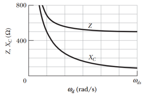
Figure 31-29 Problem 36.
Want to see the full answer?
Check out a sample textbook solution
Chapter 31 Solutions
Fundamentals Of Physics
Additional Science Textbook Solutions
Glencoe Physical Science 2012 Student Edition (Glencoe Science) (McGraw-Hill Education)
Life in the Universe (4th Edition)
Glencoe Physics: Principles and Problems, Student Edition
University Physics with Modern Physics (14th Edition)
Physics for Scientists and Engineers: A Strategic Approach, Vol. 1 (Chs 1-21) (4th Edition)
Conceptual Integrated Science


- An LRC series circuit consists of an AC voltage source with amplitude Vs = 20V and angular frequency w = 2000 rad/s, a resistor with resistance R = 10 Q, an inductor with inductance L = 20 mH, and a capacitor with capacitance C = 10 µF (all these components are connected in series). What is the voltage amplitude across the capacitor (Vc)? 70.7 V 10.1 V 1.01 V 101 V O 34.2 Varrow_forwardProblem 1: Consider the circuit depicted in the attached figure. The voltage source is an AC source of frequencyf = 55 Hz. R, C, Randomized Variables R1 = 103 Q 7. R2 = 162 Q C1 = 6.5 µF C2 = 9.5 µF C2 R, L = 0.77 H Part (a) Given the above circuit, write an expression for the total impedance Z for the circuit as a complex number. You may assume the current is a completely real phasor. Expression : Z = Select from the variables below to write your expression. Note that all variables may not be required. a, B, A, n, 0, C1, C1+, C2, d, f, g, h, i, L, m, p, P, R1, R2, t Part (b) Given the values for resistance, inductance, and capacitance above, what is the magnitude of the phasor for the impedance Z in 2. Numeric : A numeric value is expected and not an expression. |Z| = Part (c) Given the values for resistance, inductance, and capacitance above, what is the phase angle of the phasor for the impedance Z in degrees. Numeric : A numeric value is expected and not an expression. Part (d) If…arrow_forwardWhat is the impedance of a series combination of 30 2 resistor, a 2.0 µF capacitor and a 16 µF capacitor at a frequency of 9.0 kHz. Z =arrow_forward
- Consider an RC (resistor-capacitor) AC circuit with a supply voltage of Vac = 200 V, with an angular frequency, w, a resistor, R = 100 £2, and a capacitor, C. Assume the angular frequency of the power supply is set at w = 1/RC. (a) What is the impedance, Z of the circuit? (b) What is the current in the circuit? (c) What is the (peak) voltage drop across the resistor and the capacitor, respectively? (d) Draw the phasor diagram for this situation. (e) What is the phase angle between the current and the power supply voltage? (f) What would the ratio of L/C have to be if an inductor were added to the circuit in series that made the circuit purely resistive (Z = R)?arrow_forwardAn ac series circuit contains a voltage source with angular frequency of 200 rad/s and volatage amplitude V, a resistor with R=400 ohms and a capacitor with C= 1.00 x10^-5 F. If the voltage amplitude across the resistor is 40 V, what is the amplitude of the voltage across the capacitor?arrow_forwardProblem 10: A series LRC circuit has a sinusoidal voltage supplied to it at 197 kHz with a peak voltage of 270 V, a 41 k2 resistance, a 14 µF capacitor, and a 63 H inductance. What is the peak current for this circuit?arrow_forward
- An ac series circuit has an impedance of 109 02, and the phase angle between the current and the voltage of the generator is p = -88 °. The circuit contains a resistor and either a capacitor or an inductor. Find (a) the resistance R and (b) the capacitive reactance Xc or the inductive reactance XL, whichever is appropriate. (a) R = i (b) Reactance = i îarrow_forwardProblem: 3 Part (a) Calculate the impedance of the capacitor, in ohms. XC = ______ Part (b) Find the impedance of the inductor, in ohms. XL = ______arrow_forwardA series RC circuit has a resistance of 250 ΩΩ and a capacitance of 6.0 μμF. If the circuit is dirven by a 60 Hz source, find a) the capacitive reactance. b) the impedance of the circuit.arrow_forward
- A sinusoidal voltage with AVmax= 120 V and frequency w = 120 rad/s is applied to a series RLC circuit with L = 20 mH, C = 160 µF and R = 40 Q. Calculate the impedance and the maximum current in this circuit. %3Darrow_forwardFind the charge on the capacitor in an LRC-series circuit when L = q(t) = C What is the charge on the capacitor after a long time? C - h, R = 10 , C = 0.01 f, E(t) = 250 V, q(0) = 1 C, and i(0) = 0 A.arrow_forwardAn ac series circuit consists of a voltage source of frequency 60 Hz and voltage amplitude V, a 533 Ohm resistor, and a capacitor of capacitance 6.4 µF. What must be the source voltage amplitude V for the average electrical power consumed in the resistor to be 989 W? There is no inductance in the circuit. (The answer is integer.)arrow_forward
 Physics for Scientists and Engineers: Foundations...PhysicsISBN:9781133939146Author:Katz, Debora M.Publisher:Cengage Learning