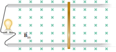
Consider the apparatus shown in Figure P30.32: a
Figure P30.32

(a)
Answer to Problem 31.58AP
Explanation of Solution
Given info: Magnetic field of system is
The emf develop in the system can be given as,
Here,
The current developed in the bar can be given as,
Here,
Substitute
Thus, the expression for current is
Conclusion:
Therefore, the expression for current as a function of
(b)
Answer to Problem 31.58AP
Explanation of Solution
Given info: Magnetic field of system is
The power delivered to the light bulb can be given as,
Here,
As the power is function of both force and speed, in order to maximize the power both force and velocity needs to be maximum. The desired condition can only be achieved if there is loss of energy whatsoever which can only be possible if the particle is in equilibrium.
Thus, the analysis model which describes the moving bar for maximum power is particle under equilibrium.
Conclusion:
Therefore, the analysis model which describes the moving bar for maximum power is particle under equilibrium.
(c)
Answer to Problem 31.58AP
Explanation of Solution
Given info: Magnetic field of system is
The magnetic force applied on the bar can be given as,
Substitute
Rearrange the above equation for
Substitute
Thus, the speed of the bar is
Conclusion:
Therefore, the speed of the bar when maximum power is delivered to the light bulb is
(d)
Answer to Problem 31.58AP
Explanation of Solution
Given info: Magnetic field of system is
The current in the light bulb can be given as from equation (1),
Substitute
Thus, the current in light bulb is
Conclusion:
Therefore, the current in light bulb when maximum power is delivered is
(e)
Answer to Problem 31.58AP
Explanation of Solution
Given info: Magnetic field of system is
The power delivered to the light bulb can be given as,
Substitute
Thus, the maximum power delivered to the light bulb is
Conclusion:
Therefore, the maximum power delivered to the light bulb will be
(f)
Answer to Problem 31.58AP
Explanation of Solution
Given info: Magnetic field of system is
The mechanical input power can be given as,
Substitute
Thus, the maximum mechanical input power is
Conclusion:
The maximum mechanical input power delivered to the bar is
(g)
Answer to Problem 31.58AP
Explanation of Solution
Given info: Magnetic field of system is
Consider the expression for speed of the bar from equation (2).
As speed of the bar depends on the resistance, therefore it will change if the resistance increases.
Conclusion:
Therefore, the velocity will change if the resistance increases.
(h)
Answer to Problem 31.58AP
Explanation of Solution
Given info: Magnetic field of system is
Consider the expression for speed of the bar from equation (2),
From the above equation, the speed will be directly proportional to the resistance if all other variables are held constant.
Thus, the speed of the bar will increase if resistance increases.
Conclusion:
Therefore, the speed of the bar will increase if the resistance increases.
(i)
Answer to Problem 31.58AP
Explanation of Solution
Given info: Magnetic field of system is
As far as the mechanical power input is concerned it only depends on the load and the velocity of the object. Since the current in electrical machinery is analogous to mechanical load, an increase in current will lead to change in mechanical load which further changes the mechanical power input.
Thus, the mechanical power input will change.
Conclusion:
Therefore, the effect of increase in resistance and current on the mechanical power input is that it will change.
(j)
Answer to Problem 31.58AP
Explanation of Solution
Given info: Magnetic field of system is
Both current and resistance can never increase as it violates Ohm’s law which says that current is inversely proportional to resistance.
In order to increase current despite increase in resistance, the load demand will increase to increase the current supply, this further increases the power.
Thus, the mechanical power input will increase if both current and resistance will increase.
Conclusion:
Thus, the mechanical power input will increase if both current and resistance will increase.
Want to see more full solutions like this?
Chapter 31 Solutions
Physics for Scientists and Engineers, Technology Update (No access codes included)
- A piece of silicon semiconductor has length L=0.01cm and cross-section in a square shape with an area of A=5×10⁻⁴cm2 . The semiconductor is doped with 1012cm−3 Phosphorus atoms and 1017cm−3 Boron atoms. An external electric field E=1.5×10⁴N/C is applied to the silicon piece along the length direction, through the cross section. What is the total current in the silicon at T=300K? Assume the mobility of silicon is 1400cm2V−1s−1 for electrons and 450cm2V−1s−1 for holes, respectively. Assume the intrinsic carrier concentration in silicon is 1010cm−3 . Give your answer in mA, rounded to 3 significant figures. Just enter the number, nothing else.arrow_forwardAn impurity with a charge of 2e is placed in a three-dimensional metal. Assume that the Friedel sum rule holds for this system, and only the scattering phase shifts from the electrons contribute to this sum (we don't need to consider ion phase shifts). This metal has a spherical Fermi surface with Fermi wave vector kF . The only degeneracy for the electrons at the Fermi surface is spin (two-fold) and angular momentum ( 2l+1 for each angular momentum l ). Ignore scattering for l>2 and assume that the scattering doesn't depend on the spin degree of freedom. Denote the scattering phase shift at the Fermi wave vector in the l -th angular momentum channel as δl(kF) . If δ0(kF)=11π31 , and δ1(kF)=π29 , what is δ2(kF)? Round your answer to three significant figures. Just enter the number, nothing else.arrow_forwardA pilot with a mass of 75 kg is flying an airplane at a true airspeed of 55m/s in air that is still relative to the ground. The pilot enters a coordinated turn of constant bank angle and constant altitude, and the pilot experiences an effective weight of 1471.5N normal to the wings of the plane. What is the rate of turn (in degrees per second) for the aircraft? Round your answer to three significant figures. Just enter the number, nothing else.arrow_forward
- Imagine you are out for a stroll on a sunny day when you encounter a lake. Unpolarized light from the sun is reflected off the lake into your eyes. However, you notice when you put on your vertically polarized sunglasses, the light reflected off the lake no longer reaches your eyes. What is the angle between the unpolarized light and the surface of the water, in degrees, measured from the horizontal? You may assume the index of refraction of air is nair=1 and the index of refraction of water is nwater=1.33 . Round your answer to three significant figures. Just enter the number, nothing else.arrow_forwardRed, yellow, green, and blue light with wavelengths of λred=700 nm , λyellow=580 nm , λgreen=520 nm , and λblue=475 nm are directed at a slit that is 20 μm wide at normal incidence. The light hits a screen 1 m behind the slit. Which color of light will have an interference minimum closest to a point 10 cm away from its central maxima? You may assume the small angle approximation sinθ≈tanθ≈θ for angles smaller than 10∘ . Just enter the wavelength of that color in nm, nothing else.arrow_forwardIn the circuit shown, the switch is initially open and the capacitor isuncharged. What will be the current through R1 the instant after the switch isclosed? Take V=10 V, R1 = 20 W, R2 = 20 W, R3 = 10 W and C = 2 mF.arrow_forward
 Physics for Scientists and Engineers: Foundations...PhysicsISBN:9781133939146Author:Katz, Debora M.Publisher:Cengage Learning
 Physics for Scientists and EngineersPhysicsISBN:9781337553278Author:Raymond A. Serway, John W. JewettPublisher:Cengage Learning
 Physics for Scientists and Engineers with Modern ...PhysicsISBN:9781337553292Author:Raymond A. Serway, John W. JewettPublisher:Cengage Learning
 Glencoe Physics: Principles and Problems, Student...PhysicsISBN:9780078807213Author:Paul W. ZitzewitzPublisher:Glencoe/McGraw-Hill
 Principles of Physics: A Calculus-Based TextPhysicsISBN:9781133104261Author:Raymond A. Serway, John W. JewettPublisher:Cengage Learning


