
Videos
A Low-Pass Filter. Figure P31.48 shows a low-pass filter (see Problem 31.47); the output voltage is taken across the capacitor in an L-R-C series circuit. Derive an expression for
Figure P31.48
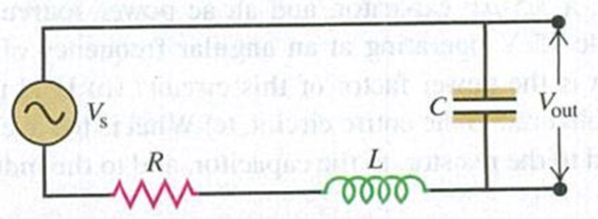
Vout/Vs, the ratio of the output and source voltage amplitudes, as a function of the angular frequency ω of the source. Show that when ω is large, this ratio is proportional to ω−2 and thus is very small, and show that the ratio approaches unity in the limit of small frequency.
Want to see the full answer?
Check out a sample textbook solution
Chapter 31 Solutions
University Physics with Modern Physics (14th Edition)
Additional Science Textbook Solutions
Conceptual Physical Science (6th Edition)
College Physics: A Strategic Approach (3rd Edition)
College Physics
Essential University Physics: Volume 2 (3rd Edition)
Lecture- Tutorials for Introductory Astronomy
The Cosmic Perspective (8th Edition)


- The RC high-pass filter shown in Figure P33.53 has a resistance R = 0.500 and a capacitance C = 613 F. What is the ratio of the amplitude of the output voltage to that of the input voltage for this filter for a source frequency of 600 Hz?arrow_forwardIn the AC circuit shown in Figure P32.3, R = 70.0 and the output voltage of the AC source is Vmax sin t. (a) If VR = 0.250 Vmax for the first time at t = 0.0100 s, what is the angular frequency of the source? (b) What is the next value of t for which VR = 0.250 Vmax? Figure P32.6 Problem 3 and 5.arrow_forwardAn PLC series circuit with R=600 , L = 30 mH. and c=0.050F is driven by an ac source whose frequency and voltage amplitude are 500 Hz and 50 V, respectively, (a) What is the impedance of the circuit? (b) What is the amplitude of the current in the circuit? (c) What is the phase angle between the emf of the source and the current?arrow_forward
- An ac source of voltage amplitude 100 V and frequency 1.0 kHz drives an PLC series circuit with R=20, L = 4.0 mH, and C=50F . (a) Determine the rms current through the circuit, (b) What are the rms voltages across the three elements? (c) What is the phase angle between the emf and the current? (d) What is the power output of the source? (e) What is the power dissipated in the resistor?arrow_forwardFor an RLC series circuit, the voltage amplitude and frequency of the source are 100 V and 500 Hz, respectively; R=500 ; and L = 0.20H . Find the average power dissipated in the resistor for the following values for the capacitance: (a) C=2.0F and (b) C=2.0F .arrow_forwardWhat is the impedance of a series combination of a 50resistor, a 5.0F capacitor, and a 10F capacitor at a frequency of 2.0 kHz?arrow_forward
- A series RLC circuit has resistance R = 50.0 and inductance L. = 0.500 H. (a) Find the circuits capacitance C if the voltage source operates at a frequency of f = 60.0 Hz and the impedance is Z = R = 50.0 . (b) What is the phase angle between the current and the voltage?arrow_forwardIn a purely inductive AC circuit as shown in Figure P21.15, Vmax = 100. V. (a) The maximum current is 7.50 A at 50.0 Hz. Calculate the inductance L. (b) At what angular frequency is the maximum current 2.50A? Figure p21.15arrow_forwardAn ac source of voltage amplitude 10 V delivers electric energy at a rate of 0.80 W when its current output is 2.5 A. What is the phase angle between the emf and the current?arrow_forward
- In an RLC series circuit, the voltage amplitude and frequency of the source are 100 V and 500 Hz, respectively, an R = 5O0. L=0.20H, and C=2.0F . (a)What is the impedance of the circuit? (b) What is the amplitude of the current from the source? (C) If the emf of the source Is given by v(tt)=(100V)sin , how does the current vary with time? (d) Repeat the calculations with C changed to 0.20F .arrow_forwardIn a purely inductive AC circuit as shown in Figure P32.6, Vmax = 100 V. (a) The maximum current is 7.50 A at 50.0 Hz. Calculate the inductance L. (b) What If? At what angular frequency is the maximum current 2.50 A? Figure P32.6 Problem 6 and 7.arrow_forwardThe emf of an ac source is given by v(t)=V0sint, where V0=100V and =200 . Find an expression that represents the output current of the source if it is connected across (a) a 20-pF capacitor, (b) a 20-mH inductor, and (c) a 50 resistor.arrow_forward
 Physics for Scientists and EngineersPhysicsISBN:9781337553278Author:Raymond A. Serway, John W. JewettPublisher:Cengage Learning
 Physics for Scientists and Engineers with Modern ...PhysicsISBN:9781337553292Author:Raymond A. Serway, John W. JewettPublisher:Cengage Learning
 Physics for Scientists and Engineers, Technology ...PhysicsISBN:9781305116399Author:Raymond A. Serway, John W. JewettPublisher:Cengage Learning
 College PhysicsPhysicsISBN:9781285737027Author:Raymond A. Serway, Chris VuillePublisher:Cengage Learning
 College PhysicsPhysicsISBN:9781305952300Author:Raymond A. Serway, Chris VuillePublisher:Cengage Learning