
Concept explainers
Videos
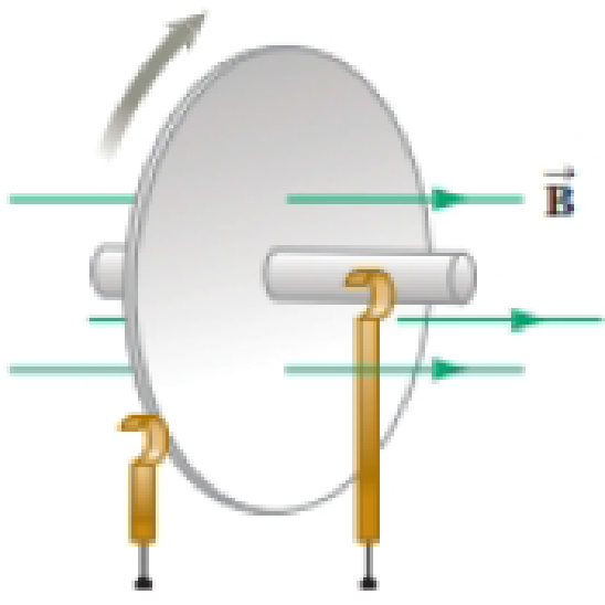
You are working for a company that manufactures motors and generators. At the end of your first day of work, your supervisor explains to you that you will be assigned to a team that is designing a new homopolar generator. You have no idea what that is, but agree wholeheartedly to the assignment. At home that evening, you go online to learn about the homopolar generator and find the following. The homopolar generator, also called the Faraday disk, is a low-voltage, high-current electric generator. It consists of a rotating
Figure P30.17

Trending nowThis is a popular solution!

Chapter 30 Solutions
Physics for Scientists and Engineers with Modern Physics
Additional Science Textbook Solutions
College Physics
Conceptual Physical Science (6th Edition)
Glencoe Physical Science 2012 Student Edition (Glencoe Science) (McGraw-Hill Education)
Introduction To Health Physics
Loose Leaf For Explorations: Introduction To Astronomy
The Cosmic Perspective (9th Edition)


- A bar magnet is attached solidly to a frictionless surface and its length is aligned with the x axis. To the right of the first magnet a short distance away is a second bar magnet with its center placed on the x axis and its length perpendicular to the x axis. The second magnet is free to move. Once placed in position at rest, which best describes the initial motion of the second magnet? O The magnet will move away from the fixed magnet. The magnet will not move. The magnet will start to rotate. O The magnet will move toward the fixed magnet.arrow_forwardYou may want to review (Page 796). For help with math skills, you may want to review: The Vector Cross Product 1 The Vector Cross Product 2 Figure P 1 of 1 Part A What is the strength of the magnetic field at point P in the figure? (Figure 1) Assume that I = 6.0 A, T1 = 1.1 cm, and r2 = 2.2 cm. Express your answer to two significant figures and include the appropriate units. B = 1 Submit Part B μà Value Request Answer Submil into the screen out of the screen What is the direction of the magnetic field at point P in the figure? Previous Answers Correct Units B ?arrow_forwardA rectangular loop with width L and a slidewire with mass m are as shown in figure 1. A uniform magnetic field B is directed perpendicular to the plane of the loop into the plane of the figure. The slidewire is given an initial speed of v0 and then released. There is no friction between the slidewire and the loop, and the resistance of the loop is negligible in comparison to the resistance R of the slidewire. (A) obtain and expression for F, the magnitude of the force exerted on the wire while it is moving at speed v. Express your answer in terms of some or all variables B, v, R, L, and m. (B) find the distance x that the wire moves before coming to rest. Express your answer in terms of some or all of the variable B, v0, R, L, and m.arrow_forward
- An iron (density ρ) rod with length L, cross sectional area A, spans across two parallel, metal train tracks. The tracks are connected to a power supply and have a potential ∆V across them. Between the tracks are placed magnets such that the B-field points directly upwards with strength B. What is the acceleration of the iron rod be the moment it starts from rest? What will acceleration be as a function of speed as it continues? Assume the contact is frictionless between the tracks and the rod so that no force of friction needs to be overcome. What will the top speed of the rod be under these conditions?arrow_forwardProblem 12: Part (a) What is the ratio I1 / I2 that gives zero field strength at the center of the loop, in terms of the variables given in the problem statement? I1/I2 = ______arrow_forwardYour physics professor is doing a demo to demonstrate Faraday’s law. He usesa 5m long wire of 10 Ohms total resistance, and he shapes it as a perfect square.Your professor places the loop in a plane perpendicular to a 2 Tesla uniformmagnetic field pointing from above into the plane of the loop. Then yourprofessor re-shaped the wire in five seconds from a square into a perfect circle.The new loop remains in the same plane.a. What is the magnitude of the average induced emf in the wire during thistime?b. Find the direction, and average magnitude of the current in the loopduring the deformation? Explain your reasoning.arrow_forward
- n a science laboratory, you rub a glass rod with silk, placing a 25-nC positive charge on it. Calculate the force on the rod due to the Earth’s magnetic field (5 x 10^(-5) T), if you throw it with a horizontal velocity of 15 m/s wesarrow_forwardFour long, parallel conductors carry equal currents of I = 5.00 A. Figure P19.49 is an end view of the conductors. The direction of the current is into the page at points A and B (indicated by the crosses) and out of the page at C and D (indicated by the dots). Calculate the magnitude and direction of the magnetic field at point P , located at the center of the square with edge of length 0.200 m.arrow_forwardA 144-Ω light bulb is connected to a conducting wire that is wrapped into the shape of a square with side length of 83.0 cm. This square loop is rotated within a uniform magnetic field of 454 mT. What is the change in magnetic flux through the loop when it rotates from a position where its area vector makes an angle of 30° with the field to a position where the area vector is parallel to the field? The loop rotates from a position where its area vector makes an angle of 30° with the field to a position where the area vector is parallel to the field in 56.3 ms. What is the induced current through the light bulb? This square loop is rotated with a frequency of 60 Hz within a uniform magnetic field of 454 mT. This means the loop makes half a revolution in 8.33 ms. What is the induced current in the light bulb when the loop rotates from a position where its area vector is opposite the magnetic field to a position where its area vector is parallel to the magnetic field?arrow_forward
- The figure below shows a conducting rod sliding along a pair of conducting rails. The conducting rails have an angle of inclination of θ=30 degrees. There is a resistor at the top of the ramp that connects the two conducting rails R=2.3Ω. The mass of the rod is 0.42 kg. The rod starts from rest at the top of the ramp at time t=0. The rails have negligible resistance and friction, and are separated by a distance L=15.7 m. There is a constant, vertically directed magnetic field of magnitude B=1.5 T. Find the emf induced in the rod as a function of its velocity down the rails. What is the emf when the velocity is 5.696E−03 m/s? .116 W What is the rod's terminal speed? 0.01138 m/s WHAT I NEED HELP WITH: A) When the rod moves at its terminal speed, what is the power dissipated in the resistor? For this I was using the equation P = V2/R and I got .00586 W which is wrong. What am I doing wrong?arrow_forwardIn an old-fashioned television, a beam of electrons is accelerated to a speed of 2.3 × 10⁶ m /s and then directed to the flat screen, a distance d = 0.05 m from the end of the accelerator, using magnets, as shown in the figure below. The mass of an electron is 9.1 × 10⁻³¹ kg. a. An electron, having just left the accelerator and traveling in the x direction, enters a region of uniform magnetic field, B = 1.5 x 10⁻⁴ T in the y direction. What is the force on the electron due to the magnetic field? Be sure to specify both the magnitude and direction. b. What is the radius of curvature of the path of the electron as it moves from the accelerator to the screen? c. With what speed does the electron hit the screen? d. How far from the center of the screen does the electron hit? That is, how far is the electron deflected by the magnetic field? В y accelerator darrow_forwardThe figure shows two closed paths wrapped around two conducting loops carrying currents i = 6.4 A and iz = 3.6 A. What is the value of the integral B ds for (a) path 1 and (b) path 2? D2arrow_forward
 Principles of Physics: A Calculus-Based TextPhysicsISBN:9781133104261Author:Raymond A. Serway, John W. JewettPublisher:Cengage Learning