EBK MACHINE ELEMENTS IN MECHANICAL DESI
6th Edition
ISBN: 9780134451947
Author: Wang
Publisher: YUZU
expand_more
expand_more
format_list_bulleted
Concept explainers
Videos
Textbook Question
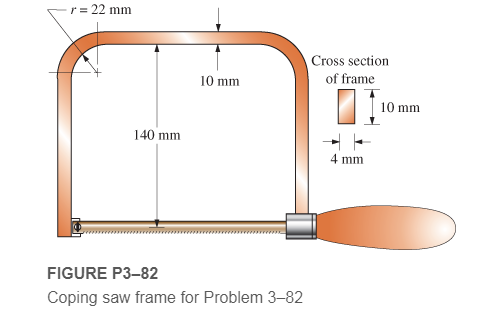
Chapter 3, Problem 82P
A coping saw frame shown in Figure P3−82 is made from SAE 1020 CD steel. A screw thread in the handle draws the blade of the saw into a tension of 120 N. Determine the resulting design factor based on yield strength in the area of the corner radii of the frame.
Expert Solution & Answer
Want to see the full answer?
Check out a sample textbook solution
Students have asked these similar questions
As shown in the figure below, moist air at T₁ = 36°C, 1 bar, and 35% relative humidity enters a heat exchanger operating at steady state
with a volumetric flow rate of 10 m³/min and is cooled at constant pressure to 22°C. Ignoring kinetic and potential energy effects,
determine:
(a) the dew point temperature at the inlet, in °C.
(b) the mass flow rate of moist air at the exit, in kg/min.
(c) the relative humidity at the exit.
(d) the rate of heat transfer from the moist air stream, in kW.
(AV)1, T1
P₁ = 1 bar
11
= 35%
120
T₂=22°C
P2 = 1 bar
Air at T₁-24°C, p₁-1 bar, 50% relative humidity enters an insulated chamber operating at steady state with a mass flow rate of 3
kg/min and mixes with a saturated moist air stream entering at T₂-7°C, p2-1 bar. A single mixed stream exits at T3-17°C, p3-1 bar.
Neglect kinetic and potential energy effects
Step 1
Your answer is correct.
Determine mass flow rate of the moist air entering at state 2, in kg/min.
m2 = 2.1
Hint
kg/min
Using multiple attempts will impact your score.
5% score reduction after attempt 2
Step 2
Determine the relative humidity of the exiting stream.
Փ3 =
i
%
Attempts: 1 of 3 used
A reservoir at 300 ft elevation has a 6-in.-diameter discharge pipe located 50 ft below the surface. The pipe is 600 ft long and drops in elevation to 150 ft where the flow discharges to the atmosphere. The pipe is made of riveted steel with a roughness height of 0.005 ft.
Determine the flow rate without a head loss
Determine the flow rate with the pipe friction head loss.
(hints: Since the velocity is not known for part b and the Reynolds number and friction factor depend on velocity, you will need to iterate to find the solution. A good first guess is the velocity from part (a))
Chapter 3 Solutions
EBK MACHINE ELEMENTS IN MECHANICAL DESI
Ch. 3 - A tensile member in a machine structure is...Ch. 3 - Compute the stress in a round bar having a...Ch. 3 - Compute the stress in a rectangular bar having...Ch. 3 - A link in a packaging machine mechanism has a...Ch. 3 - Two circular rods support the 3800 lb weight of a...Ch. 3 - A tensile load of 5.00 kN is applied to a square...Ch. 3 - An aluminum rod is made in the form of a hollow...Ch. 3 - Compute the stress in the middle portion of rod AC...Ch. 3 - Compute the forces in the two angled rods in...Ch. 3 - If the rods from Problem 9 are circular, determine...
Ch. 3 - Repeat Problems 9 and 10 if the angle is 15 .Ch. 3 - Figure P312 shows a small truss spanning between...Ch. 3 - The truss shown in Figure P313 spans a total space...Ch. 3 - Figure P314 shows a short leg for a machine that...Ch. 3 - Consider the short compression member shown in...Ch. 3 - Refer Figure P38 . Each of the pins at A, B, and C...Ch. 3 - Compute the shear stress in the pins connecting...Ch. 3 - Prob. 18PCh. 3 - Prob. 19PCh. 3 - Prob. 20PCh. 3 - Prob. 21PCh. 3 - Compute the torsional shear stress in a circular...Ch. 3 - If the shaft of Problem 22 is 850 mm long and is...Ch. 3 - Compute the torsional shear stress due to a torque...Ch. 3 - Compute the torsional shear stress in a solid...Ch. 3 - Compute the torsional shear stress in a hollow...Ch. 3 - Compute the angle of twist for the hollow shaft of...Ch. 3 - A square steel bar, 25 mm on a side and 650 mm...Ch. 3 - A 3.00 in-diameter steel bar has a flat milled on...Ch. 3 - A commercial steel supplier lists rectangular...Ch. 3 - A beam is simply supported and carries the load...Ch. 3 - For each beam of Problem 31, compute its weight if...Ch. 3 - For each beam of Problem 31, compute the maximum...Ch. 3 - For the beam loading of Figure P334, draw the...Ch. 3 - For the beam loading of Figure P334, design the...Ch. 3 - Figure P336 shows a beam made from 4 in schedule...Ch. 3 - Select an aluminum I-beam shape to carry the load...Ch. 3 - Figure P338 represents a wood joist for a...Ch. 3 - For Problems 39 through 50, draw the free-body...Ch. 3 - Prob. 40PCh. 3 - For Problems 39 through 50, draw the free-body...Ch. 3 - Prob. 42PCh. 3 - Prob. 43PCh. 3 - Prob. 44PCh. 3 - For Problems 39 through 50, draw the free-body...Ch. 3 - For Problems 39 through 50, draw the free-body...Ch. 3 - For Problems 39 through 50, draw the free-body...Ch. 3 - For Problems 4850, draw the free-body diagram of...Ch. 3 - For Problems 4850, draw the free-body diagram of...Ch. 3 - Prob. 50PCh. 3 - Compute the maximum tensile stress in the bracket...Ch. 3 - Compute the maximum tensile and compressive...Ch. 3 - For the lever shown in Figure P353 (a), compute...Ch. 3 - Compute the maximum tensile stress at sections A...Ch. 3 - Prob. 55PCh. 3 - Refer to Figure P38. Compute the maximum tensile...Ch. 3 - Prob. 57PCh. 3 - Refer to P342. Compute the maximum stress in the...Ch. 3 - Refer to P343. Compute the maximum stress in the...Ch. 3 - Prob. 60PCh. 3 - Figure P361 shows a valve stem from an engine...Ch. 3 - The conveyor fixture shown in Figure P362 carries...Ch. 3 - For the flat plate in tension in Figure P363,...Ch. 3 - For Problems 64 through 68, compute the maximum...Ch. 3 - For Problems 64 through 68, compute the maximum...Ch. 3 - For Problems 64 through 68, compute the maximum...Ch. 3 - For Problems 64 through 68, compute the maximum...Ch. 3 - Prob. 68PCh. 3 - Figure P369 shows a horizontal beam supported by a...Ch. 3 - Prob. 70PCh. 3 - Prob. 71PCh. 3 - The beam shown in Figure P372 is a stepped, flat...Ch. 3 - Figure P373 shows a stepped, flat bar having a...Ch. 3 - Figure P374 shows a bracket carrying opposing...Ch. 3 - Prob. 75PCh. 3 - Figure P376 shows a lever made from a rectangular...Ch. 3 - For the lever in P376, determine the maximum...Ch. 3 - Figure P378 shows a shaft that is loaded only in...Ch. 3 - Prob. 79PCh. 3 - Prob. 80PCh. 3 - A hanger is made from ASTM A36 structural steel...Ch. 3 - A coping saw frame shown in Figure P382 is made...Ch. 3 - Prob. 83PCh. 3 - Figure P384 shows a hand garden tool used to break...Ch. 3 - Figure P385 shows a basketball backboard and goal...Ch. 3 - Prob. 86P
Knowledge Booster


Learn more about
Need a deep-dive on the concept behind this application? Look no further. Learn more about this topic, mechanical-engineering and related others by exploring similar questions and additional content below.Similar questions
- Air at T₁-24°C, p₁-1 bar, 50% relative humidity enters an insulated chamber operating at steady state with a mass flow rate of 3 kg/min and mixes with a saturated moist air stream entering at T₂-7°C, p2-1 bar. A single mixed stream exits at T3-17°C, p3-1 bar. Neglect kinetic and potential energy effects Step 1 Your answer is correct. Determine mass flow rate of the moist air entering at state 2, in kg/min. m2 = 2.1 Hint kg/min Using multiple attempts will impact your score. 5% score reduction after attempt 2 Step 2 Determine the relative humidity of the exiting stream. Փ3 = i % Attempts: 1 of 3 usedarrow_forward25 mm Brass core E = 105 GPa 0 = 20.9 x 10 °C PROBLEM 2.49 The aluminum shell is fully bonded to the brass core and the assembly is unstressed at a temperature of 15°C. Considering only axial deformations, determine the stress in the aluminum when the temperature reaches 195°C. 60 mm Aluminum shell E = 70 GPa a = 23.6 × 10°Carrow_forwardThis is an old practice exam. The answers are OAB = 19.10 ksi OBC = 2.228 ksi OCD = −2.865 ksi v = 0.2792delta Ltot = 0.01585 in (increase) but whyarrow_forward
- A random poly(styrene-butadiene) copoly- mer has a number-average molecular weight of 350,000 g/mol and a degree of polymerization of 5000. Compute the fraction of styrene and buta- diene repeat units in this copolymer. H H | | -C-C- 방 Harrow_forwardDesign and assemble on the fluidsim (or a draft) the Hydraulic Drive Circuit, with the following characteristics: (a) Sequential operation, pressure, for the advance and return of the cylinders (according to the proper operation for the device) controlled by a directional 4x3 way, closed center; (b) Speed control for the cylinders, according to the load signal; (c) Pressure counterbalance for cylinder A, in order to compensate for the weight of the assembly.arrow_forwardThis is an old exam practice question. The answer is Pmax = 218.8 kN normal stress governs but why?arrow_forward
- Moist air initially at T₁ = 140°C, p₁ = 4 bar, and p₁ = 50% is contained in a 2.0-m³ closed, rigid tank. The tank contents are cooled to T₂ 35°C. Step 1 Determine the temperature at which condensation begins, in °C.arrow_forwardAir at T₁ = 24°C, p₁ = 1 bar, 50% relative humidity enters an insulated chamber operating at steady state with a mass flow rate of 3 kg/min and mixes with a saturated moist air stream entering at T2=7°C, p₂ = 1 bar. A single mixed stream exits at T3-17°C, p3=1 bar. Neglect kinetic and potential energy effectsarrow_forwardHand calculation of cooling loadarrow_forward
- An HEV has a 24kW battery. How many miles can it go on electricity alone at 40 mph on a flat straight road with no headwind? Assume the rolling resistance factor is 0.018 and the Coefficient of Drag (aerodynamic) is 0.29 the frontal area is 2.25m^2 and the vehicle weighs 1618 kg.arrow_forwardAs shown in the figure below, moist air at T₁ = 36°C, 1 bar, and 35% relative humidity enters a heat exchanger operating at steady state with a volumetric flow rate of 10 m³/min and is cooled at constant pressure to 22°C. Ignoring kinetic and potential energy effects, determine: (a) the dew point temperature at the inlet, in °C. (b) the mass flow rate of moist air at the exit, in kg/min. (c) the relative humidity at the exit. (d) the rate of heat transfer from the moist air stream, in kW. (AV)1, T1 P₁ = 1 bar 11 = 35% 120 T₂=22°C P2 = 1 bararrow_forwardThe inside temperature of a wall in a dwelling is 19°C. If the air in the room is at 21°C, what is the maximum relative humidity, in percent, the air can have before condensation occurs on the wall?arrow_forward
arrow_back_ios
SEE MORE QUESTIONS
arrow_forward_ios
Recommended textbooks for you
 Mechanics of Materials (MindTap Course List)Mechanical EngineeringISBN:9781337093347Author:Barry J. Goodno, James M. GerePublisher:Cengage Learning
Mechanics of Materials (MindTap Course List)
Mechanical Engineering
ISBN:9781337093347
Author:Barry J. Goodno, James M. Gere
Publisher:Cengage Learning
Stresses Due to Fluctuating Loads Introduction - Design Against Fluctuating Loads - Machine Design 1; Author: Ekeeda;https://www.youtube.com/watch?v=3FBmQXfP_eE;License: Standard Youtube License