
Concept explainers
Videos
Write a set of mesh equations for the circuit in Fig. 3.110. Use MATLAB to determine the mesh currents.
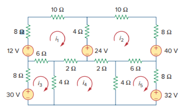
Figure 3.110
For Prob. 3.66.
Write the mesh current equations, and find the mesh currents in the circuit of Figure 3.110 using mesh analysis and MATLAB.
Answer to Problem 66P
The matrix form of mesh current equations is
Explanation of Solution
Given data:
Refer Figure 3.110 in the textbook for mesh analysis.
Calculation:
Apply Kirchhoff’s voltage law to loop 1 with current
Apply Kirchhoff’s voltage law to loop 2 with current
Apply Kirchhoff’s voltage law to loop 3 with current
Apply Kirchhoff’s voltage law to loop 4 with current
Apply Kirchhoff’s voltage law to loop 5 with current
Represent the equations (1), (2), (3), (4), and (5) in matrix form.
MATLAB code:
Write the MATLAB code to solve the equations (1), (2), (3), (4), and (5) as follows in MATLAB code editor, and save it as “node366”, and then run the code. The result will shows in main command window.
syms i1 i2 i3 i4 i5
eq1 = 30*i1 -4*i2 -6*i3 -2*i4 +0*i5 == -12;
eq2 = -4*i1 +30*i2 +0*i3 -2*i4 -6*i5 == -16;
eq3 = -6*i1 +0*i2 +18*i3 -4*i4 +0*i5 == 30;
eq4 = -2*i1 -2*i2 -4*i3 +12*i4 -4*i5 == 0;
eq5 = 0*i1 -6*i2 +0*i3 -4*i4 +18*i5 == -32;
sol = solve([eq1, eq2, eq3, eq4, eq5], [i1, i2, i3, i4, i5]);
val1 = sol.i1;
val2 = sol.i2;
val3 = sol.i3;
val4 = sol.i4;
val5 = sol.i5;
i1= sprintf('%.4f A',val1)
i2= sprintf('%.4f A',val2)
i3= sprintf('%.4f A',val3)
i4= sprintf('%.4f A',val4)
i5= sprintf('%.4f A',val5)
The output in command window:
i1 = '-0.2779 A'
i2 = '-1.0488 A'
i3 = '1.4682 A'
i4 = '-0.4761 A'
i5 = '-2.2332 A'
Conclusion:
Therefore, the matrix form of mesh current equations is,
And the value of currents
Want to see more full solutions like this?
Chapter 3 Solutions
EE 98: Fundamentals of Electrical Circuits - With Connect Access


- In Superposition theorem, while considering a source, all other voltage sources are. Select one: a. short circuited O b. open circuited O c. removed from the circuit O d. change its positionarrow_forwardRefer to the given circuit below. Determine the Norton Equivalent Current Source if R3 is to be analyzed.arrow_forwardUse superposition to calculate the voltage Vo, if Is = 35, R = 18 and Vs = 32. %3D ww ww Is Vsarrow_forward
- Consider the following circuit, with voltage source and current source. Find the voltage across R3 using superposition method Find Thevenis equivalent circuit seen by Rs i. i. Circuit Parameters Vs = 6 V RI Is = 4 A R2 Vs R3 Ri =2 0 %3D R2 = 2 0 %3D Is R3 = 2 0arrow_forwardCircuits: Superposition Theoremarrow_forwardFor the following electrical circuit in R3 = 649ohm determine by the method of Superposition theorem: the electric current, Voltage and Power dissipated in the circuitarrow_forward
- Vo For the following circuit, If R, = 400 N, and R, = 350 n then %3D R1 Vx vo 300 N 20 V Vx R2 100arrow_forward3- For the circuit shown below, Find the Norton's equivalent circuit at terminals (a-b). 60 N 25 N 4.7 kfN Da 10 V a R, 47 kN R 2.7kN R3 18 ma 15 V 30 N 10 V 3.9 kfl E 180 V (I) (II)arrow_forwardFor the shown values and polarities provided, using SUPERPOSITION: a. Find the contribution to Vx from the voltage source only b. Find the contribution to V3 from the current source only 5000 5002 + 9V Vx 1 6mA 1kQ 5002arrow_forward
- For the circuit below, use nodal analysis to find the voltages VA, VB, Vc, Vp and VE: (Provide your calculations and reasoning for your answer.) 12 R7 500 0.25Adc R1 330 R2 1.5k Vc R3 1.2k Vp VB VA 0.5Adc R4 R5 R6 2.5k 2k 3karrow_forwardConsider the circuit diagram below. Solve for the voltage at node b and the current through R5 using node analysis. You can use CircuitJS to verify your result, but you are not required to. R2 2 ΚΩ R1 1 ΚΩ IS1 50 mA R3 5 ΚΩ R4 4 ΚΩ b R5 1 ΚΩ J E1 40Varrow_forwardYou are required to analyze the circuit given below, using Thevenin's theorem. You can use any technique to simplify the circuit if required (without disturbing Vo). Please address the followings: a) Compute open circuit voltage Voc across a-b terminals. b) Compute short circuit current (Iah) by short-circuiting the terminals a-b. c) Compute RTH using the values of Voc and Ish. [1 mark] d) Recompute RTH by inserting 1A-current source across a-b terminals. 0.25 Vo 20 18V 3Ω. Voarrow_forward
 Introductory Circuit Analysis (13th Edition)Electrical EngineeringISBN:9780133923605Author:Robert L. BoylestadPublisher:PEARSON
 Delmar's Standard Textbook Of ElectricityElectrical EngineeringISBN:9781337900348Author:Stephen L. HermanPublisher:Cengage Learning
 Programmable Logic ControllersElectrical EngineeringISBN:9780073373843Author:Frank D. PetruzellaPublisher:McGraw-Hill Education
 Fundamentals of Electric CircuitsElectrical EngineeringISBN:9780078028229Author:Charles K Alexander, Matthew SadikuPublisher:McGraw-Hill Education
 Electric Circuits. (11th Edition)Electrical EngineeringISBN:9780134746968Author:James W. Nilsson, Susan RiedelPublisher:PEARSON
 Engineering ElectromagneticsElectrical EngineeringISBN:9780078028151Author:Hayt, William H. (william Hart), Jr, BUCK, John A.Publisher:Mcgraw-hill Education,