
Vector Mechanics for Engineers: Statics, 11th Edition
11th Edition
ISBN: 9780077687304
Author: Ferdinand P. Beer, E. Russell Johnston Jr., David Mazurek
Publisher: McGraw-Hill Education
expand_more
expand_more
format_list_bulleted
Concept explainers
Videos
Textbook Question
Chapter 3, Problem 3.153RP
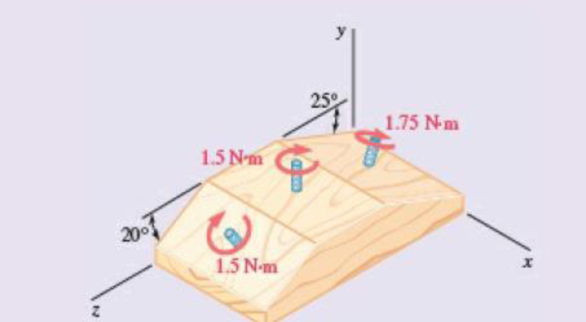
In a manufacturing operation, three holes are drilled simultaneously in a workpiece. If the holes are perpendicular to the surfaces of the workpiece, replace the couples applied to the drills with a single equivalent couple, specifying its magnitude and the direction of its axis.
Expert Solution & Answer
Want to see the full answer?
Check out a sample textbook solution
Students have asked these similar questions
Replace the two couples shown with a single equivalent couple, specifying its magnitude and the direction of its axis.
Replace the two couples shown by a single equivalent couple.
Force P and couple M are applied at A as shown.
1. Suppose an equivalent system was made such that only force at B and a couple are present. What gives the magnitude of force at B and the couple in the equivalent system?
2. If the force P and couple M is to be replaced with a single force, where is the point of application of this single force along bar ABCD in order to have the same external effect as the original set of force P and couple M? (How many m to the left or right of B)
Chapter 3 Solutions
Vector Mechanics for Engineers: Statics, 11th Edition
Ch. 3.1 - 3.1 A crate of mass 80 kg is held in the position...Ch. 3.1 - 3.2 A crate of mass 80 kg is held in the position...Ch. 3.1 - It is known that a vertical force of 200 lb is...Ch. 3.1 - A 300-N force is applied at A as shown. Determine...Ch. 3.1 - A 300-N force is applied at A as shown. Determine...Ch. 3.1 - Prob. 3.6PCh. 3.1 - Prob. 3.7PCh. 3.1 - Prob. 3.8PCh. 3.1 - Rod AB is held in place by the cord AC. Knowing...Ch. 3.1 - Rod AB is held in place by the cord AC. Knowing...
Ch. 3.1 - 3.11 and 3.12The tailgate of a car is supported by...Ch. 3.1 - 3.11 and 3.12The tailgate of a car is supported by...Ch. 3.1 - 3.13 and 3.14It is known that the connecting rod...Ch. 3.1 - 3.13 and 3.14It is known that the connecting rod...Ch. 3.1 - 3.15 Form the vector products B × C and B′ × C,...Ch. 3.1 - Prob. 3.16PCh. 3.1 - 3.17 A plane contains the vectors A and B....Ch. 3.1 - Prob. 3.18PCh. 3.1 - Prob. 3.19PCh. 3.1 - 3.20 Determine the moment about the origin O of...Ch. 3.1 - Before the trunk of a large tree is felled, cables...Ch. 3.1 - The 12-ft boom AB has a fixed end A. A steel cable...Ch. 3.1 - A 200-N force is applied as shown to the bracket...Ch. 3.1 - Prob. 3.24PCh. 3.1 - A 6-ft-long fishing rod AB is securely anchored in...Ch. 3.1 - A precast concrete wall section is temporarily...Ch. 3.1 - In Prob. 3.22, determine the perpendicular...Ch. 3.1 - Prob. 3.28PCh. 3.1 - Prob. 3.29PCh. 3.1 - In Prob. 3.25, determine the perpendicular...Ch. 3.1 - In Prob. 3.25, determine the perpendicular...Ch. 3.1 - In Prob. 3.26, determine the perpendicular...Ch. 3.1 - In Prob. 3.26, determine the perpendicular...Ch. 3.1 - Determine the value of a that minimizes the...Ch. 3.2 - 3.35 Given the vectors P = 2i + 3j − k, Q = 5i −...Ch. 3.2 - Form the scalar product B C and use the result...Ch. 3.2 - Prob. 3.37PCh. 3.2 - Prob. 3.38PCh. 3.2 - Knowing that the tension in cable AC is 280 lb,...Ch. 3.2 - Knowing that the tension in cable AD is 180 lb,...Ch. 3.2 - Ropes AB and BC are two of the ropes used to...Ch. 3.2 - Ropes AB and BC are two of the ropes used to...Ch. 3.2 - The 20-in. tube AB can slide along a horizontal...Ch. 3.2 - Solve Prob. 3.43 for the position corresponding to...Ch. 3.2 - Prob. 3.45PCh. 3.2 - Prob. 3.46PCh. 3.2 - A crane is oriented so that the end of the 25-m...Ch. 3.2 - 3.48The 25-m crane boom AO lies in the yz plane....Ch. 3.2 - To loosen a frozen valve, a force F with a...Ch. 3.2 - 3.50When a force F is applied to the handle of the...Ch. 3.2 - 3.51 To lift a heavy crate, a man uses a block and...Ch. 3.2 - Prob. 3.52PCh. 3.2 - A farmer uses cables and winch pullers B and E to...Ch. 3.2 - Solve Prob. 3.53 when the tension in cable AB is...Ch. 3.2 - Prob. 3.55PCh. 3.2 - Prob. 3.56PCh. 3.2 - The frame ACD is hinged at A and D and is...Ch. 3.2 - In Prob. 3.57, determine the moment about the...Ch. 3.2 - The triangular plate ABC is supported by...Ch. 3.2 - 3.60The triangular plate ABC is supported by...Ch. 3.2 - Prob. 3.61PCh. 3.2 - Prob. 3.62PCh. 3.2 - Two forces F1 and F2 in space have the same...Ch. 3.2 - Prob. 3.64PCh. 3.2 - Prob. 3.65PCh. 3.2 - In Prob. 3.57, determine the perpendicular...Ch. 3.2 - In Prob. 3.58, determine the perpendicular...Ch. 3.2 - In Prob. 3.59, determine the perpendicular...Ch. 3.2 - In Prob. 3.60, determine the perpendicular...Ch. 3.3 - Two 80-N forces are applied as shown to the...Ch. 3.3 - Prob. 3.71PCh. 3.3 - 3.72 Four pegs are attached to a board as shown....Ch. 3.3 - Four pegs of the same diameter are attached to a...Ch. 3.3 - A piece of plywood in which several holes are...Ch. 3.3 - Prob. 3.75PCh. 3.3 - Prob. 3.76PCh. 3.3 - 3.77If P = 20 lb in the figure, replace the three...Ch. 3.3 - 3.78 Replace the two couples shown with a single...Ch. 3.3 - Prob. 3.79PCh. 3.3 - Shafts A and B connect the gear box to the wheel...Ch. 3.3 - A 500-N force is applied to a bent plate as shown....Ch. 3.3 - Prob. 3.82PCh. 3.3 - A dirigible is tethered by a cable attached to its...Ch. 3.3 - A 30-lb vertical force P is applied at A to the...Ch. 3.3 - A worker tries to move a rock by applying a 360-N...Ch. 3.3 - A worker tries to move a rock by applying a 360-N...Ch. 3.3 - The shearing forces exerted on the cross section...Ch. 3.3 - Prob. 3.88PCh. 3.3 - Three control rods attached to a lever ABC exert...Ch. 3.3 - A rectangular plate is acted upon by the force and...Ch. 3.3 - While tapping a hole, a machinist applies the...Ch. 3.3 - A hexagonal plate is acted upon by the force P and...Ch. 3.3 - Replace the 250-kN force P with an equivalent...Ch. 3.3 - A 2.6-kip force is applied at point D of the...Ch. 3.3 - Replace the 150-N force with an equivalent...Ch. 3.3 - To keep a door closed, a wooden stick is wedged...Ch. 3.3 - A 46-lb force F and a 2120-lbin. couple M are...Ch. 3.3 - A 110-N force acting in a vertical plane parallel...Ch. 3.3 - Prob. 3.99PCh. 3.3 - Prob. 3.100PCh. 3.4 - Prob. 3.101PCh. 3.4 - Prob. 3.102PCh. 3.4 - Prob. 3.103PCh. 3.4 - Five separate force-couple systems act at the...Ch. 3.4 - The weights of two children sitting at ends A and...Ch. 3.4 - Three stage lights are mounted on a pipe as shown....Ch. 3.4 - A beam supports three loads of given magnitude and...Ch. 3.4 - A 6 12-in. plate is subjected to four loads as...Ch. 3.4 - Prob. 3.109PCh. 3.4 - To test the strength of a 625 500-mm suitcase,...Ch. 3.4 - Prob. 3.111PCh. 3.4 - Pulleys A and B are mounted on bracket CDEF. The...Ch. 3.4 - 3.113 A truss supports the loading shown....Ch. 3.4 - A couple of magnitude M = 80 lbin. and the three...Ch. 3.4 - A couple M and the three forces shown are applied...Ch. 3.4 - A machine component is subjected to the forces and...Ch. 3.4 - Solve Prob. 3.116, assuming that P = 60 N.Ch. 3.4 - As follower AB rolls along the surface of member...Ch. 3.4 - A machine component is subjected to the forces...Ch. 3.4 - Two 150-mm-diameter pulleys are mounted on line...Ch. 3.4 - As an adjustable brace BC is used to bring a wall...Ch. 3.4 - In order to unscrew the tapped faucet A, a plumber...Ch. 3.4 - Assuming = 60 in Prob. 3.122, replace the two...Ch. 3.4 - Four forces are applied to the machine component...Ch. 3.4 - A blade held in a brace is used to tighten a screw...Ch. 3.4 - A mechanic uses a crowfoot wrench to loosen a bolt...Ch. 3.4 - Prob. 3.127PCh. 3.4 - Prob. 3.128PCh. 3.4 - Four signs are mounted on a frame spanning a...Ch. 3.4 - Prob. 3.130PCh. 3.4 - A concrete foundation mat of 5-m radius supports...Ch. 3.4 - Determine the magnitude and the point of...Ch. 3.4 - Prob. 3.133PCh. 3.4 - A piece of sheet metal is bent into the shape...Ch. 3.4 - Prob. 3.135PCh. 3.4 - Prob. 3.136PCh. 3.4 - Two bolts at A and B are tightened by applying the...Ch. 3.4 - Two bolts at A and B are tightened by applying the...Ch. 3.4 - Prob. 3.139PCh. 3.4 - A flagpole is guyed by three cables. If the...Ch. 3.4 - 3.141 and 3.142Determine whether the...Ch. 3.4 - 3.141 and 3.142Determine whether the...Ch. 3.4 - Replace the wrench shown with an equivalent system...Ch. 3.4 - Show that, in general, a wrench can be replaced...Ch. 3.4 - Show that a wrench can be replaced with two...Ch. 3.4 - Show that a wrench can be replaced with two...Ch. 3 - A 300-N force P is applied at point A of the bell...Ch. 3 - A winch puller AB is used to straighten a fence...Ch. 3 - A small boat hangs from two davits, one of which...Ch. 3 - Prob. 3.150RPCh. 3 - A single force P acts at C in a direction...Ch. 3 - 3.152 A small boat hangs from two davits, one of...Ch. 3 - In a manufacturing operation, three holes are...Ch. 3 - A 260-lb force is applied at A to the rolled-steel...Ch. 3 - Prob. 3.155RPCh. 3 - A 77-N force F1 and a 31-Nm couple M1 are applied...Ch. 3 - Three horizontal forces are applied as shown to a...Ch. 3 - While using a pencil sharpener, a student applies...
Knowledge Booster


Learn more about
Need a deep-dive on the concept behind this application? Look no further. Learn more about this topic, mechanical-engineering and related others by exploring similar questions and additional content below.Similar questions
- Shafts A and B connect the gear box to the wheel assemblies of a tractor, and shaft C connects it to the engine. Shafts A and B lie in the vertical yz plane, while shaft C is directed along the x axis.Replace the couples applied to the shafts by a single equivalent couple, specifying its magnitude and the direction of its axis.arrow_forwardThe two shafts of a speed-reducer unit are subjected to couples of magnitude M1 = 15 lb·ft and M2 = 3 lb·ft, respectively. Replace the two couples with a single equivalent couple, specifying its magnitude and the direction of its axis.arrow_forwardShafts A and B connect the gear box to the wheel assemblies of a tractor, and shaft C connects it to the engine. Shafts A and B lie in the vertical yz plane, while shaft C is directed along the x axis. Replace the couples applied to the shafts by a single equivalent couple, specifying its magnitude and the direction of its axis.arrow_forward
- The two shafts of a speed-reducer unit are subjected to couples of magnitude M1 =15 lb.ft and M2=3 lb.ft, respectively. Replace the two couples with a single equivalent couple, specifying its magnitude and the direction of its axis.arrow_forward5. A force-couple system is as follows. Note that all dimensions are in ft. Also draw all pertinent diagrams as part of your solution. a. Scenario 1: If the force system shown is to be replaced by a force-couple system consisting of a force acting at A and a clockwise moment equal to 300 lb-ft, what is the magnitude and sense of M,? b. Scenario 2: If M, = 90 lbft counterclockwise, what should be the magnitude, direction, and point of application along AB of a force F that should be added to the system of forces shown if the system is equivalent to a single horizontal 10-lb force acting east at point B? 4.00 150 lb 70 200 lb 80 lb 3.00 3.00 70° 3.00 50 lb 200 lb Ma B 2.00 130 lb 30 Answer: a. M,=269.3083 lb-ft CW b. F= 194.0149 lb, 52.0548° S of W d= 0.3876 ft right of Aarrow_forwardA couple acts on the gear teeth as shown in the figure below. Replace it by an equivalent couple having a pair of forces that act through (a) points A and B.arrow_forward
- The forces shown form a couple. Which ONE of the following equations can be used to replace the shown couple with an equivalent couple acting at points A and B. HINT: Choose clockwise as negative and counterclockwise as positive. 50 mm AB 40 N 200 mm 40 N Ⓒa. 40 N(200 mm) - F(50 mm) = 0 b. -40 N(200 mm) + F(50 mm) = c. +40 N(200 mm) + F(50 mm) = 0 d. 50 N(200 mm) - F(40 mm) = 0 e. 40 N(50 mm) - F(200 mm) = 0 Clear my choicearrow_forward(a) Determine a wrench equivalent force-couple system (b) Specify the x and y coordinates of the point where the wrench crosses the xy plane please answer aarrow_forwardWhich of the systems are equivalent to the couple in (a)?arrow_forward
- Identify the conditions under which a given system of forces can be reduced to a single force (Check all that apply) O One can replace the force -couple system at O by a single force R acting along a new line of action if R and M, are mutually tangential. One can replace the force -couple system at O by a single force R acting along a new line of action if R and M, are mutually perpendicular. O One can replace the force -couple system at O by a single force R acting along a new →R line of action if R and M, are mutually parallel.arrow_forwardProblem 3a: Find the magnitude of the resultant moment (couple) from the system of couples below. Also find the direction angles of the resultant couple. 15 lb 15 lb D 20 lb 18 lb 10 in. 8 in. 15 in. 18 lb 20 lbarrow_forwardUsing a force couple system, solve the following by replacing the given. 1. point A 2. point B 3. If the force system is to be replaced by an equivalent force at an arbitrary point ?, how far from ? (distance ?) should the force be applied?arrow_forward
arrow_back_ios
SEE MORE QUESTIONS
arrow_forward_ios
Recommended textbooks for you
 Elements Of ElectromagneticsMechanical EngineeringISBN:9780190698614Author:Sadiku, Matthew N. O.Publisher:Oxford University Press
 Mechanics of Materials (10th Edition)Mechanical EngineeringISBN:9780134319650Author:Russell C. HibbelerPublisher:PEARSON
 Thermodynamics: An Engineering ApproachMechanical EngineeringISBN:9781259822674Author:Yunus A. Cengel Dr., Michael A. BolesPublisher:McGraw-Hill Education
 Control Systems EngineeringMechanical EngineeringISBN:9781118170519Author:Norman S. NisePublisher:WILEY
 Mechanics of Materials (MindTap Course List)Mechanical EngineeringISBN:9781337093347Author:Barry J. Goodno, James M. GerePublisher:Cengage Learning
 Engineering Mechanics: StaticsMechanical EngineeringISBN:9781118807330Author:James L. Meriam, L. G. Kraige, J. N. BoltonPublisher:WILEY
Elements Of Electromagnetics
Mechanical Engineering
ISBN:9780190698614
Author:Sadiku, Matthew N. O.
Publisher:Oxford University Press
Mechanics of Materials (10th Edition)
Mechanical Engineering
ISBN:9780134319650
Author:Russell C. Hibbeler
Publisher:PEARSON
Thermodynamics: An Engineering Approach
Mechanical Engineering
ISBN:9781259822674
Author:Yunus A. Cengel Dr., Michael A. Boles
Publisher:McGraw-Hill Education
Control Systems Engineering
Mechanical Engineering
ISBN:9781118170519
Author:Norman S. Nise
Publisher:WILEY
Mechanics of Materials (MindTap Course List)
Mechanical Engineering
ISBN:9781337093347
Author:Barry J. Goodno, James M. Gere
Publisher:Cengage Learning
Engineering Mechanics: Statics
Mechanical Engineering
ISBN:9781118807330
Author:James L. Meriam, L. G. Kraige, J. N. Bolton
Publisher:WILEY
Introduction To Engg Mechanics - Newton's Laws of motion - Kinetics - Kinematics; Author: EzEd Channel;https://www.youtube.com/watch?v=ksmsp9OzAsI;License: Standard YouTube License, CC-BY