
(a)
Show that the given circuit satisfies Kirchhoff’s current law at junction terminals x-y.
(a)
Answer to Problem 1P
Yes, the given circuit satisfies Kirchhoff’s current law at junction terminals x-y.
Explanation of Solution
Given data:
Refer to Figure given in the textbook.
The voltage delivered by the source is 120 V.
PSPICE Simulation:
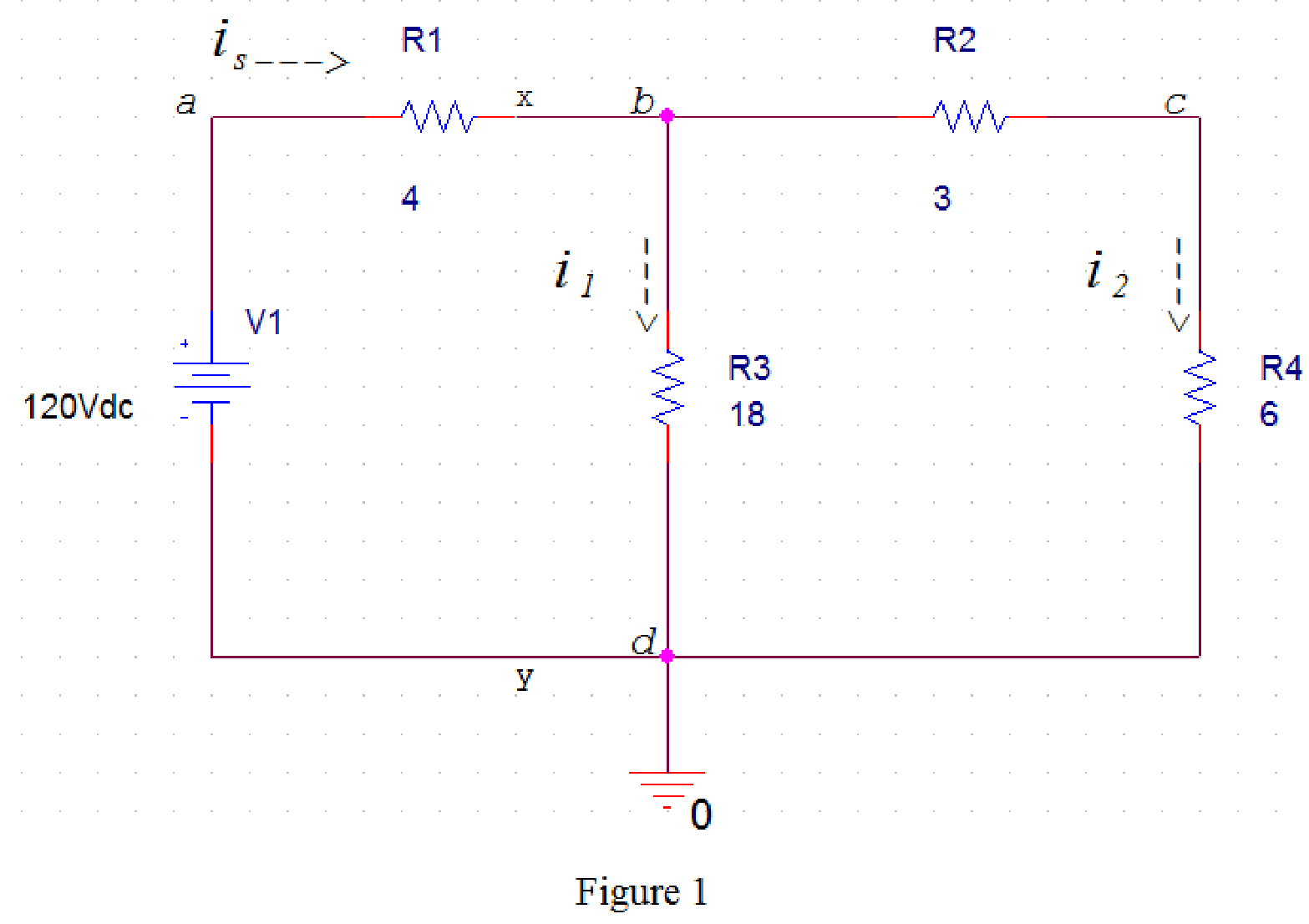
Draw the circuit diagram in PSpice as shown in Figure 1.
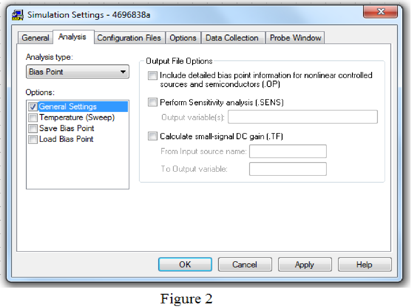
Save the circuit and provide the Simulation Settings as shown in Figure 2.
Now run the simulation and the results will be displayed as shown in Figure 3 by enabling the “Enable Bias Current Display” icon.
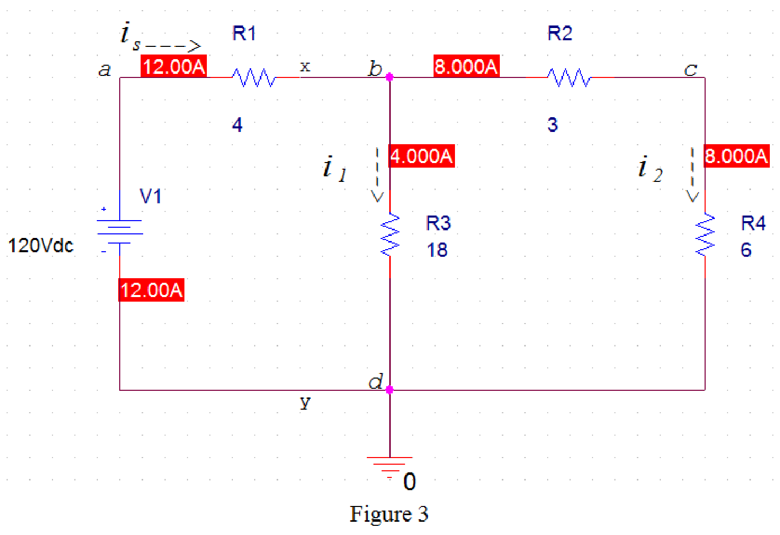
From Figure 3, source current is=12 A and the node currents i1=4 A and i2=8 A.
Kirchhoff’s current law states that the current entering the node is equal to the current leaving the node.
In Figure 3, apply Kirchhoff current law at node b. Therefore,
−is+i1+i2=0 (1)
Rearrange the equation (1) as follows,
is=i1+i2 (2)
Substitute 12 A for is, 4 A for i1 and 8 A for i2 in equation (2).
12 A=4 A+8 A12 A=12 A12 A−12 A=0
Hence, the given circuit satisfies Kirchhoff’s current law at junction terminals x-y.
Conclusion:
Thus, yes, the given circuit satisfies Kirchhoff’s current law at junction terminals x-y.
(b)
Show that the given circuit satisfies Kirchhoff’s voltage law.
(b)
Answer to Problem 1P
Yes, the given circuit satisfies Kirchhoff’s voltage law.
Explanation of Solution
Given data:
Refer to Figure given in the textbook.
Voltage delivered by the source is 120 V.
PSPICE Simulation:
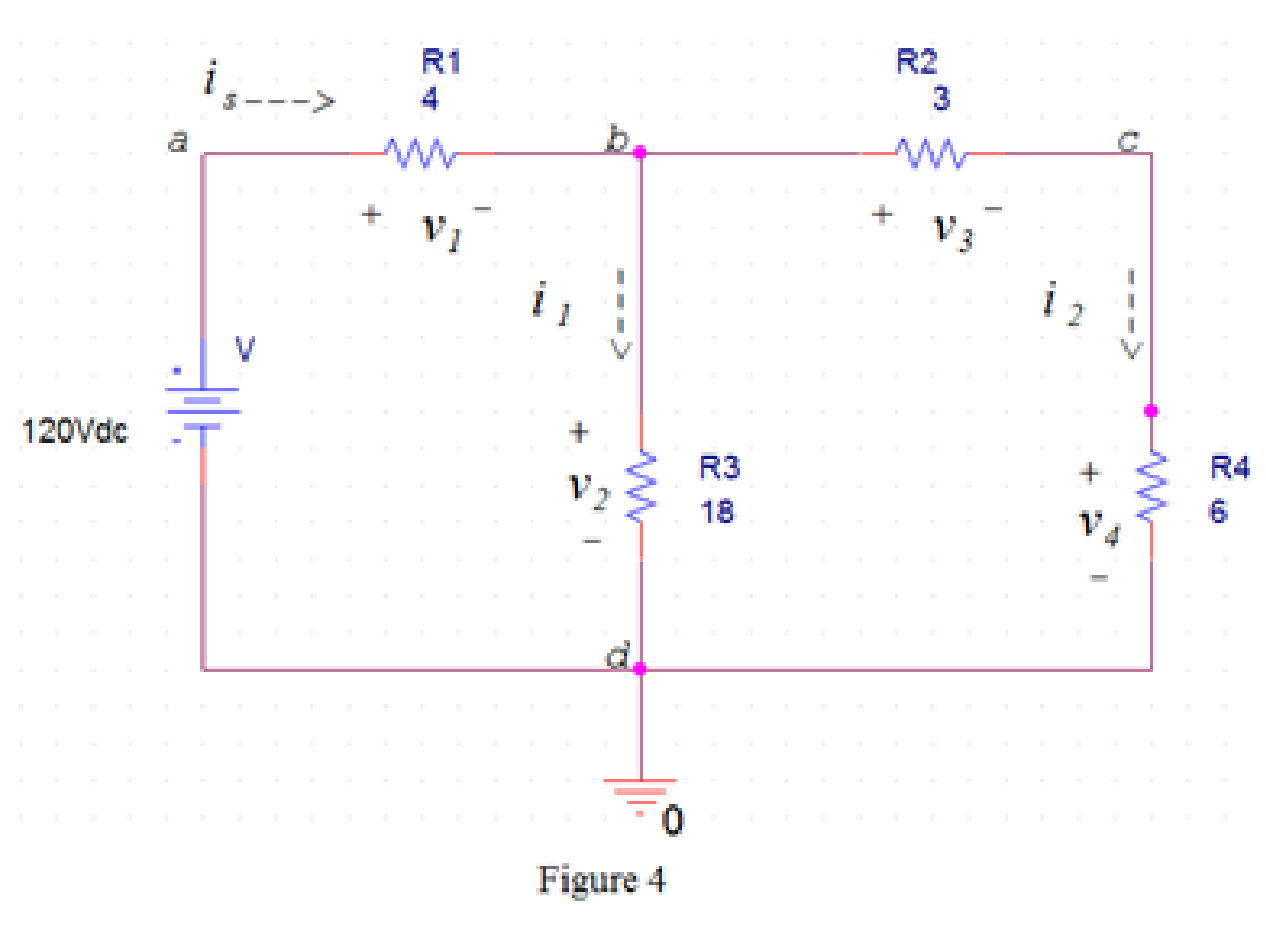
Draw the circuit diagram in PSpice as shown in Figure 4.
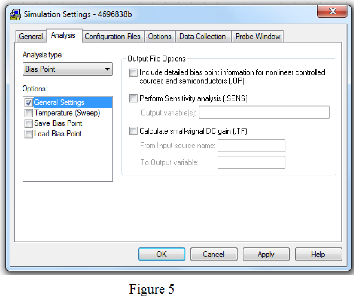
Save the circuit and provide the Simulation Settings as shown in Figure 5.
Now run the simulation and the results will be displayed as shown in Figure 3 by enabling the “Enable Bias Current Display” icon and “Enable Bias Voltage Display” icon.
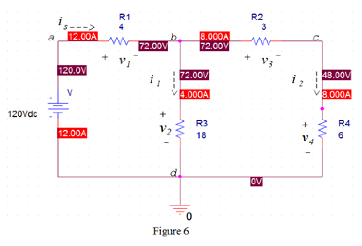
From Figure 6, the voltage v1 across the 4 Ω resistor is,
The voltage
The voltage
The voltage
Kirchhoff’s voltage law states that the sum of the voltage rise around any closed loop must be equal to the sum of voltage drops around that loop.
In Figure 6, apply Kirchhoff’s voltage law to the loop abda.
From Figure 6, the source voltage
Substitute
In Figure 6, apply Kirchhoff’s voltage law to the loop bcdb.
Substitute
In Figure 6, apply Kirchhoff’s voltage law to the loop abcda.
Substitute
Hence, the given circuit satisfies Kirchhoff’s voltage law around every closed loop.
Conclusion:
Thus, yes, the given circuit satisfies Kirchhoff’s voltage law.
Want to see more full solutions like this?
Chapter 3 Solutions
Electrical Circuits and Modified MasteringEngineering - With Access

- Three speech signals are TDM multiplexed with a high-quanty music signal. It each speech signal is sampled at 16 kHz and PCM quantized by 8 bits/sample, while the music signal is sampled at 64 kHz with the same PCM quantizer. 1. Draw the block diagram of this TDM. 2. Calculate the output bit rate of this TDM.arrow_forward3- For the network below determine the value of R for maximum power to R (use Thevenin equivalent) and determine the value of maximum power R₁ 1.2Ω E + 12 V I D 10 A R₂60 6Ω Rarrow_forwardPlease solve this problem in detail to understandarrow_forward
- Q3: (40 Marks) Single phase full bridge voltage source inverter has an RLC load with R-1002, L-31.5mH and C=112µF. The inverter frequency is 60Hz and de input voltage is 220V. (a) Express the instantaneous load current in Fourier series to third harmonic. (b) Calculate the RMS load current at the fundamental frequency (n=1). (c) Calculate the load power due to fundamental component (n=1).arrow_forward12.3 Express each of the waveforms in Fig. P12.3 (on page 667) in terms of step functions and then determine its Laplace transform. [Recall that the ramp function is related to the step function by r(t − T) = (t − T) u(t − T).] Assume that all waveforms are zero for t<0. - - -arrow_forwardEvaluate each of the following integraarrow_forward
- With the aid of suitable diagrams, describe the benefits that antenna arrays have over singleelement antennas, with their applicationsarrow_forwardExplain what is meant by an electric dipole antenna, sketch its radiation pattern, state itsdirectivity and describe its main applicationsarrow_forwardEstimate the length required for a half-waveelectric dipole antenna for transmitting/receiving EM waves at 800 MHz (this is in the UHFbandwidth of 470 to 860 MHz, used for UK TV transmissions).arrow_forward
- If the voltage waveform in Fig. 6.68 is applied to a 50-mH inductor, find the inductor current i(1). Assume i(0) = 0.arrow_forwardQ3/A 8-pole, 3-phase, 50 Hz induction motor, running at 725 r.p.m, rotor is star connected its resistance and reactance 0.25 and 1.5 ohm per phase, the emf between slip rings is 100, find the rotor current per phase, power factor, synchronous speed, slip and rotor frequencyarrow_forward440 v, 4-pole, 3-phase, 50 Hz, star stator connected induction motor, full load speed 1425 r.p.m, rotor impedance 0.5+4.55ohm and rotor/stator ratio 0.8 calculate 1) starting torque, (2) rotor current (3) the value of external resistance to add to give maximum starting torque (4) power factor at maximum torque.arrow_forward
 Introductory Circuit Analysis (13th Edition)Electrical EngineeringISBN:9780133923605Author:Robert L. BoylestadPublisher:PEARSON
 Delmar's Standard Textbook Of ElectricityElectrical EngineeringISBN:9781337900348Author:Stephen L. HermanPublisher:Cengage Learning
 Programmable Logic ControllersElectrical EngineeringISBN:9780073373843Author:Frank D. PetruzellaPublisher:McGraw-Hill Education
 Fundamentals of Electric CircuitsElectrical EngineeringISBN:9780078028229Author:Charles K Alexander, Matthew SadikuPublisher:McGraw-Hill Education
 Electric Circuits. (11th Edition)Electrical EngineeringISBN:9780134746968Author:James W. Nilsson, Susan RiedelPublisher:PEARSON
 Engineering ElectromagneticsElectrical EngineeringISBN:9780078028151Author:Hayt, William H. (william Hart), Jr, BUCK, John A.Publisher:Mcgraw-hill Education,