Concept explainers
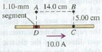
A straight wire carries a 10.0-A current (Fig. E28.9). ABCD is a rectangle with point D in the middle of a 1.10-mm segment of the wire and point C in the wire. Find the magnitude and direction of the magnetic field due to this segment at (a) point A; (b) point B; (c) point C.
Figure E28.9

Learn your wayIncludes step-by-step video

Chapter 28 Solutions
University Physics with Modern Physics, Volume 2 (Chs. 21-37); Mastering Physics with Pearson eText -- ValuePack Access Card (14th Edition)
Additional Science Textbook Solutions
College Physics
Essential University Physics (3rd Edition)
Physics for Scientists and Engineers: A Strategic Approach, Vol. 1 (Chs 1-21) (4th Edition)
Sears And Zemansky's University Physics With Modern Physics
College Physics (10th Edition)
The Cosmic Perspective Fundamentals (2nd Edition)
- Two infinitely long current-carrying wires run parallel in the xy plane and are each a distance d = 11.0 cm from the y axis (Fig. P30.83). The current in both wires is I = 5.00 A in the negative y direction. a. Draw a sketch of the magnetic field pattern in the xz plane due to the two wires. What is the magnitude of the magnetic field due to the two wires b. at the origin and c. as a function of z along the z axis, at x = y = 0? FIGURE P30.83arrow_forwardDetermine the initial direction of the deflection of charged particles as they enter the magnetic fields as shown in Figure P22.2. Figure P22.2.arrow_forwardAn electron in a TV CRT moves with a speed of 6.0107 m/s, in a direction perpendicular to Earth's field, which has a strength of 5.0105 T. (a) What strength electric field must be applied perpendicular to the Earth’s field to make the election moves in a straight line? (b) If this is done between plates separated by 1.00 cm, what is the voltage applied? (Note that TVs are usually surrounded by a ferromagnetic material to shield against external magnetic fields and avoid the need for such a collection,)arrow_forward
- The magnitude of the magnetic field 50 cm from a long, thin, straight wire is 8.0T . What is the current through the long wire?arrow_forwardThe Hall effect finds important application in the electronics industry. It is used to find the sign and density of the carriers of electric current in semiconductor chips. The arrangement is shown in Figure P22.66. A semiconducting block of thickness t and width d carries a current I in the x direction. A uniform magnetic field B is applied in the y direction. If the charge carriers are positive, the magnetic force deflects them in the z direction. Positive charge accumulates on the top surface of the sample and negative charge on the bottom surface, creating a downward electric field. In equilibrium, the downward electric force on the charge carriers balances the upward magnetic force and the carriers move through the sample without deflection. The Hall voltage ΔVH = Vc − Va between the top and bottom surfaces is measured, and the density of the charge carriers can be calculated from it. (a) Demonstrate that if the charge carriers are negative the Hall voltage will be negative. Hence, the Hall effect reveals the sign of the charge carriers, so the sample can be classified as p-type (with positive majority charge carriers) or n-type (with negative). (b) Determine the number of charge carriers per unit volume n in terms of I, t, B, ΔVH, and the magnitude q of the carrier charge. Figure P22.66arrow_forwardAn infinitely long wire carrying a current I is bent at a right angle as shown in Figure P22.30. Determine the magnetic field at point P, located a distance x from the corner of the wire. Figure P22.30arrow_forward
- Why is the following situation impossible? Figure P28.46 shows an experimental technique for altering the direction of travel for a charged particle. A particle of charge q = 1.00 C and mass m = 2.00 1015 kg enters the bottom of the region of uniform magnetic field at speed = 2.00 105 m/s, with a velocity vector perpendicular to the field lines. The magnetic force on the particle causes its direction of travel to change so that it leaves the region of the magnetic field at the top traveling at an angle from its original direction. The magnetic field has magnitude B = 0.400 T and is directed out of the page. The length h of the magnetic field region is 0.110 m. An experimenter performs the technique and measures the angle at which the particles exit the top of the field. She finds that the angles of deviation are exactly as predicted. Figure P28.46arrow_forwardFigure P30.10 shows a circular current-carrying wire. Using the coordinate system indicated (with the z axis out of the page), state the direction of the magnetic field at points A and B.arrow_forwardFigure CQ19.7 shows a coaxial cable carrying current I in its inner conductor and a return current of the same magnitude in the opposite direction in the outer conductor. The magnetic field strength at r = r0 is Find the ratio B/B0, at (a) r = 2r0 and (b) r = 4r0. Figure CQ19.7arrow_forward
- In Figure P22.43, the current in the long, straight wire is I1 = 5.00 A and the wire lies in the plane of the rectangular loop, which carries a current I2 = 10.0 A. The dimensions in the figure are c = 0.100 m, a = 0.150 m, and = 0.450 m. Find the magnitude and direction of the net force exerted on the loop by the magnetic field created by the wire. Figure P22.43 Problems 43 and 44.arrow_forwardAt a particular instant an electron is traveling west to east with a kinetic energy of 10 keV. Earth's magnetic field has a horizontal component of 1.8105 T north and a vertical component of 5.0105 T down. (a) What is the path of the election? (b) What is the radius of curvature of the path?arrow_forwardA long, solid, cylindrical conductor of radius 3.0 cm carries a current of 50 A distributed uniformly over its cross-section. Plot the magnetic field as a function of the radial distance r from the center of the conductor.arrow_forward
 Principles of Physics: A Calculus-Based TextPhysicsISBN:9781133104261Author:Raymond A. Serway, John W. JewettPublisher:Cengage Learning
 Physics for Scientists and Engineers with Modern ...PhysicsISBN:9781337553292Author:Raymond A. Serway, John W. JewettPublisher:Cengage Learning
 Physics for Scientists and Engineers: Foundations...PhysicsISBN:9781133939146Author:Katz, Debora M.Publisher:Cengage Learning
 Physics for Scientists and Engineers, Technology ...PhysicsISBN:9781305116399Author:Raymond A. Serway, John W. JewettPublisher:Cengage Learning
 College PhysicsPhysicsISBN:9781305952300Author:Raymond A. Serway, Chris VuillePublisher:Cengage Learning
 College PhysicsPhysicsISBN:9781285737027Author:Raymond A. Serway, Chris VuillePublisher:Cengage Learning


