
Videos
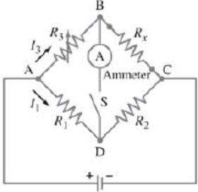
A Wheatstone bridge is a type of “bridge circuit” used to make measurements of resistance. The unknown resistance to be measured. Rx, is placed in the circuit with accurately known resistances R1, R2, and R3 (Fig. 26–65). One of these, R3, is a variable resistor which is adjusted so that when the switch is closed momentarily, the ammeter Ⓐ shows zero current flow. (a) Determine Rx in terms of R1, R2, and R3. (b) If a Wheatstone bridge is “balanced” when R1 = 630 Ω, R2 = 972 Ω, and R3 = 78.611 Ω, what is the value of the unknown resistance?
FIGURE 26–65 Problems 71 and 72. Wheatstone bridge.
Want to see the full answer?
Check out a sample textbook solution
Chapter 26 Solutions
Modified Mastering Physics without Pearson eText-- Instant Access -- for Physics for Scientists & Engineers with Modern Physics
Additional Science Textbook Solutions
The Cosmic Perspective
Physics: Principles with Applications
Modern Physics
University Physics Volume 1
Conceptual Integrated Science
College Physics: A Strategic Approach (4th Edition)


- () THE FOLLOWING QUESTIONS ARE BASED ON THE INFORMATION GIVEN HERE, R3 ww The emf source, E = 2.1 V, of the circuit shown in the figure has negligible internal resistance. The resistors have resistances R = 1.91 and R = 5.9N. The capacitor has a capacitance C = 5.8 uF. R1 B) What is the charge Q on the capacitor in units of microcoulomb? Answer:arrow_forwardB) An ammeter with resistance ‘RA’ is connected in series with resistance R=101 ohms. The applied voltage V= 201.2V. Determine the error (E) & percentage error (%E) in the current measurement due to loading effect of ammeter when- (i) RA =0.2Ωarrow_forwardPower Po = To AV, is delivered to a resistor of resistance Ro- If the resistance is doubled (Ruew=2Ro) while the voltage is adjusted such that the current is constant, what are the ratios (a) Pnew/Po and (b) AVnew/AV? If, instead, the resis- tance is held constant while P = 2P, what are the ratios (c) AVnew/AVo, and (d) Inew/Io? newarrow_forward
- (LEGIBLY PLS) In the given circuit, find (a) the current through the 8.0ohm resistor and (b) the total rate ofdissipation of electrical energy in the 8-ohm resistor and in the internal resistance of the batteries. (c) What is the rate of production of electrical energy and (d) the rate of consumption of electrical energy?arrow_forward4) b) The circuit of figure given below shows a capacitor, two ideal batteries, two resistors, and a switch S. Initially S has been open for a long time. If it is then closed for a long time, what is the change in the charge on the capacitor? Assume C=10 µF, E1=1 V, Ez=2.2 V, Rı=0.2 Q, and R2=0.4 Q.arrow_forwardThe IGCSE class is investigating electromagnets. The electromagnets are made by wrapping insulated wire around a soft-iron core. The wire is connected to a power pack. Fig. 2.1 shows the arrangement. power pack soft-iron core paper clip Fig. 2.1 Two students studied how the number of paper clips that an electromagnet can hold up depends on the potential difference across the coll. (a) Complete Fig. 2.1 by adding a voltmeter, connected to measure the p.d. across the coil.arrow_forward
- (6) Suppose two electrical resistors with resistance R₁> 0 and R₂ > 0 are wired in parallel in a circuit: R₁ ww R₂ 1 1 1 + Then the combined resistance R, measured in ohms (2), is given by R R₁ R₂ ƏR ƏR (a) Find and after solving for R (e.g., R= ...). ƏR₁ ƏR₂ (b) Describe how an increase in R₁ with R₂ held constant will change R. (Will R increase or decrease?) (c) Describe how a decrease in R₂ with R₁ held constant will hange R. (Will R increase or decrease?)arrow_forward(III) A 10.0-m length of wire consists of 5.0 m of copperfollowed by 5.0 m of aluminum, both of diameter 1.4 mm.A voltage difference of 95 mV is placed across the compositewire. (a) What is the total resistance (sum) of the two wires?(b) What is the current through the wire? (c) What are thevoltages across the aluminum part and across the copper part?arrow_forward(b) 1. A platinum resistance sensor has a resistance of 100 2 at 0 °C and a temperature coefficient of resistance (oc) of 4 x 10 "C. If the resistance of the sensor is 125 O, find the corresponding temperature of the sensor. ii. A variable dielectric capacitive displacement sensor consists of two square metal plates of side 5 cm, separated by a gap of 1 mm. A sheet of dielectric material 1 mm thick and of the same area as the plates can be slide between them as shown in Figure Q.4b. Given that the dielectric constant of air is 1 and that of the dielectric material is 4, calculate the capacitance of the sensor when the input displacement x-0.0 cm, 2.5 cm and 5,0 cm. Figure Q4barrow_forward
- (b) Consider the circuit in figure 2 below. 20 10 6V 6V 80 50 Figure 2 30 Y Calculate the (i) (ii) current through the 80 resistor p.d. across the points XY.arrow_forward(II) Eight identical bulbs are connected in series across a120-V line. (a) What is the voltage across each bulb? (b) Ifthe current is 0.45 A, what is the resistance of each bulb,and what is the power dissipated in each?arrow_forward(b) A circuit is shown in Figure 1. Given that the current, I = 0.500 A and resistance, R = 12.02. E + R 2R www 2R Figure 1 (i) Determine the current in the battery. (ii) Determine ε. [3 Marks] A [3 Marks] 24Varrow_forward
