College Physics: A Strategic Approach (3rd Edition)
3rd Edition
ISBN: 9780321879721
Author: Randall D. Knight (Professor Emeritus), Brian Jones, Stuart Field
Publisher: PEARSON
expand_more
expand_more
format_list_bulleted
Videos
Textbook Question
Chapter 26, Problem 2CQ
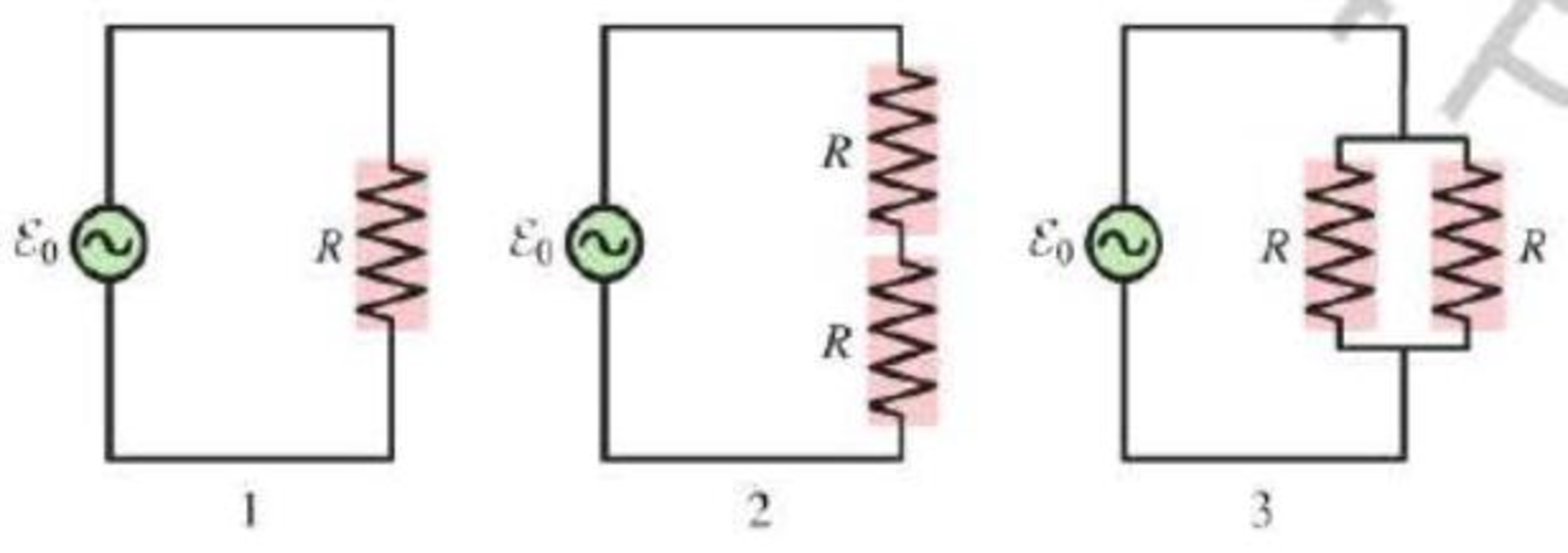
Consider the three circuits in Figure Q26.2. Rank in order, from largest to smallest, the average total powers P1 to P3 dissipated by all the resistors in each circuit. Explain.
Figure Q26.2
Expert Solution & Answer
Want to see the full answer?
Check out a sample textbook solution
Students have asked these similar questions
The figure displays two circuits with a charged capacitor that is to be discharged through a resistor when a switch is closed. In figure (a)
below, R₁ = 21.7 Q and C₁ = 5.08 µF. In figure (b) below, R₂ = 10.5 Q and C₂ = 8.00 μF. The ratio of the initial charges on the two
capacitors is 902/901 = 1.82. At time t = 0, both switches are closed. At what time t do the two capacitors have the same charge?
Number
i 0.188
Units
00
ms
(a)
(b)
Q. A capacitor with an initial potential difference
of 100 V is discharged through a resistor when a
switch between them is closed at t= 0. At t=10.0
s, the potential difference across the capacitor is
1.00 V. (a) What is the time constant of the circuit?
(b) What is the potential difference across the
capacitor at t =17.0 s?
R
In the figure, these three resistors are connected to a voltage source so that R2=4.75Ω and R3=11Ω are in parallel with one another and that combination is in series with R1=1.25Ω.
a. Calculate the power being dissipated by the third resistor R3, in watts.
b. Find the total power supplied by the source, in watts.
Chapter 26 Solutions
College Physics: A Strategic Approach (3rd Edition)
Ch. 26 - Identical resistors are connected to separate 12 V...Ch. 26 - Consider the three circuits in Figure Q26.2. Rank...Ch. 26 - Most battery-powered devices wont work if you put...Ch. 26 - If a lightbulb is connected to a 120 V, 60 Hz...Ch. 26 - A soldering gun contains a transformer that lowers...Ch. 26 - A 12 V DC power supply is connected to the primary...Ch. 26 - Figure Q26.7 shows three wires wrapped around an...Ch. 26 - Women usually have higher resistance of their arms...Ch. 26 - If you work out enough to visibly increase the...Ch. 26 - The peak current through a capacitor is 2.0 A....
Ch. 26 - Consider the four circuits in Figure Q26.14. Rank...Ch. 26 - Prob. 15CQCh. 26 - Prob. 16CQCh. 26 - Figure Q26.17 shows two inductors and the...Ch. 26 - The peak current passing through an inductor is...Ch. 26 - Consider the four circuits in Figure Q26.19. Rank...Ch. 26 - The tuning circuit in a radio uses an RLC circuit....Ch. 26 - The resonance frequency of a driven RLC circuit is...Ch. 26 - Consider the four circuits in Figure Q26.22. They...Ch. 26 - Prob. 23MCQCh. 26 - An inductor is connected to an AC generator. As...Ch. 26 - A capacitor is connected to an AC generator. As...Ch. 26 - An AC source is connected to a series combination...Ch. 26 - An AC source is connected to a series combination...Ch. 26 - The circuit shown in Figure Q26.28 has a resonance...Ch. 26 - At resonance, a driven RLC circuit has VC = 5.0 V,...Ch. 26 - A driven RLC circuit has VC = 5.0V, VR = 7.0 V,...Ch. 26 - A 200 resistor is connected to an AC source with...Ch. 26 - Figure P26.2 shows voltage and current graphs for...Ch. 26 - A resistor dissipates 2.00 W when the rms voltage...Ch. 26 - The heating element of a hair dryer dissipates...Ch. 26 - A toaster oven is rated at 1600 W for operation at...Ch. 26 - A small electric space heater uses a wire that has...Ch. 26 - A generator produces 40 MW of power and sends it...Ch. 26 - Soles of hoots that are designed to protect...Ch. 26 - The primary coil of a transformer is connected to...Ch. 26 - A soldering iron uses an electric current in a...Ch. 26 - A power pack charging a cell phone battery has an...Ch. 26 - A neon sign transformer has a 450 W AC output with...Ch. 26 - Prob. 13PCh. 26 - A science hobbyist has purchased a surplus...Ch. 26 - A generator produces 250 kW of electric power at...Ch. 26 - In an old house, the wires leading lo a 120 V...Ch. 26 - A typical American family uses 1000 kWh of...Ch. 26 - The wiring in the wall of your house to and from...Ch. 26 - The following appliances are connected to a single...Ch. 26 - Your refrigerator uses 220 W when the compressor...Ch. 26 - A 60 W (120 V) night light is turned on for an...Ch. 26 - Suppose you leave a 110 W television and two 100 W...Ch. 26 - The manufacturer of an electric table saw claims...Ch. 26 - John is changing a lightbulb in a lamp, Its a warm...Ch. 26 - In some countries AC outlets near bathtubs are...Ch. 26 - If you touch the terminal of a battery, the small...Ch. 26 - A person standing barefoot on the ground 20 m from...Ch. 26 - Electrodes used to make electrical measurements of...Ch. 26 - A fisherman has netted a torpedo ray. As he picks...Ch. 26 - Problems 30 and 31 concern a high-voltage...Ch. 26 - Problems 30 and 31 concern a high-voltage...Ch. 26 - A 0.30 F capacitor is connected across an AC...Ch. 26 - A 20 F capacitor is connected across an AC...Ch. 26 - The peak current through a capacitor is 10.0 mA....Ch. 26 - A 20 nF capacitor is connected across an AC...Ch. 26 - A capacitor is connected to a 15 kHz oscillator...Ch. 26 - The peak current through a capacitor is 8.0 mA...Ch. 26 - Prob. 38PCh. 26 - A 20 mH inductor is connected across an AC...Ch. 26 - The peak current through an inductor is 10.0 mA....Ch. 26 - A 500 H inductor is connected across an AC...Ch. 26 - An inductor is connected to a 15 kHz oscillator...Ch. 26 - The peak current through an inductor is 12.5 mA...Ch. 26 - A 2.0 mH inductor is connected in parallel with a...Ch. 26 - An FM radio station broadcasts at a frequency of...Ch. 26 - The inductor in the RLC tuning circuit of an AM...Ch. 26 - At what frequency f do a 1.0 F capacitor and a 1.0...Ch. 26 - What capacitor in series with a 100 resistor and...Ch. 26 - What inductor in series with a 100 resistor and a...Ch. 26 - A series RLC circuit has a 200 kHz resonance...Ch. 26 - An RLC circuit with a 10 F capacitor is connected...Ch. 26 - A series KLC circuit consists of a 280 resistor,...Ch. 26 - Electric outlets in England are 230 V. Alice...Ch. 26 - The voltage-to-current ratio in the primary coil...Ch. 26 - A 15-km-long, 230 kV aluminum transmission line...Ch. 26 - The voltage across a 60 F capacitor is described...Ch. 26 - Prob. 57GPCh. 26 - An electronics hobbyist is building a radio set to...Ch. 26 - For the circuit of Figure P26.59 a. What is the...Ch. 26 - For the circuit of Figure P26.60 a. What is the...Ch. 26 - An RLC circuit consists of a 48 resistor, a 200 F...Ch. 26 - Cell Membrane Resistance The capacitance of...Ch. 26 - Cell Membrane Resistance The capacitance of...Ch. 26 - Cell Membrane Resistance The capacitance of...Ch. 26 - Cell Membrane Resistance The capacitance of...Ch. 26 - Halogen Bulbs Halogen bulbs have some differences...Ch. 26 - Halogen Bulbs Halogen bulbs have some differences...Ch. 26 - Halogen Bulbs Halogen bulbs have some differences...Ch. 26 - Halogen Bulbs Halogen bulbs have some differences...
Additional Science Textbook Solutions
Find more solutions based on key concepts
51. I A tennis player hits a ball 2.0 m above the ground. The ball leaves his racquet with a speed of 20.0 m/s ...
Physics for Scientists and Engineers: A Strategic Approach with Modern Physics (4th Edition)
Why do very light gases such as hydrogen not exist in Earth's atmosphere but do exist in the atmospheres of gia...
College Physics
The pV-diagram of the Carnot cycle.
Sears And Zemansky's University Physics With Modern Physics
A block is moving to the left on a frictionless, horizontal table. A hand exerts a constant horizontal force on...
Tutorials in Introductory Physics
3. What is free-fall, and why does it make you weightless? Briefly describe why astronauts are weightless in th...
The Cosmic Perspective (8th Edition)
A fire hose for use in urban areas must be able to shoot a stream of water to a maximum height of 33 m. The wat...
Physics for Scientists and Engineers with Modern Physics
Knowledge Booster


Learn more about
Need a deep-dive on the concept behind this application? Look no further. Learn more about this topic, physics and related others by exploring similar questions and additional content below.Similar questions
- A student makes a homemade resistor from a graphite pencil 5.00 cm long, where the graphite is 0.05 mm indiameter. The resistivity of the graphite is =1.38102/m . The homemade resistor is place inseries with a switch, a 10.00-mF capacitor and a 0.50-V power source, (a) What is the BC time constant of the circuit? (b) What is the potential drop across the pencil 1.00 s after the switch is closed?arrow_forwardA flashing lamp in a Christmas earring is based on an RC discharge of a capacitor through its resistance. The effective duration of the flash is 0.250 s, during which it produces an average 0.500 W from an average 3.00 V. (a) What energy does it dissipate? (b) How much charge moves through the lamp? (c) Find the capacitance, (d) What is the resistance of the lamp? (Since average values are given for some quantities, the shape of the pulse profile is not needed.)arrow_forwardConsider a series RC circuit as in Figure P28.38 for which R = 1.00 M, C = 5.00 F, and = 30.0 V. Find (a) the time constant of the circuit and (b) the maximum charge on the capacitor after the switch is thrown closed. (c) Find the current in the resistor 10.0 s after the switch is closed.arrow_forward
- The circuit shown in Figure P28.78 is set up in the laboratory to measure an unknown capacitance C in series with a resistance R = 10.0 M powered by a battery whose emf is 6.19 V. The data given in the table are the measured voltages across the capacitor as a function of lime, where t = 0 represents the instant at which the switch is thrown to position b. (a) Construct a graph of In (/v) versus I and perform a linear least-squares fit to the data, (b) From the slope of your graph, obtain a value for the time constant of the circuit and a value for the capacitance. v(V) t(s) In (/v) 6.19 0 5.56 4.87 4.93 11.1 4.34 19.4 3.72 30.8 3.09 46.6 2.47 67.3 1.83 102.2arrow_forwardA battery with voltage Vb=12.0 V is connected to resistors R1=11.0 ohm, R2=9.00 ohm, and R3=10.0 ohm, as shown in the figure. Calculate the total power Pb provided by the battery. Pb=?W Calculate the power P1 dissipated by the resistor R1. P1=W Calculate the power P2 dissipated by the resistor R2. P2=W Calculate the power P3 dissipated by the resistor R3. P3=Warrow_forwardConsider the following RC circuit with a 5 MQ resistor and 1000 nF capacitor in series. The battery provides a potential of 10 V before the switch is closed at time t=0, the capacitor is uncharged. a. what's the time constant? b. what fraction of the final charge Qf is on the capacitor at t=30 s? C. what fraction of the initial current Io is still flowing at t=30 s? E +1arrow_forward
- In the circuit diagram R1 = 5R and R2 = 15R, where R = 24 Ω. The power dissipated in resistor 2 is P = 3.7 W. A.What is the voltage across the battery in volts? b. How much power, Ps, is the source supplying, in watts?arrow_forward51. The switch in Figure P27.5la closes when AV, >AV and opens when AV.arrow_forwardFigure given below displays two circuits with a charged capacitor that is to be discharged through a resistor when a switch is closed. In figure(a), R1 = 16 Q and C1= 8 µF. In figure(b), R2 = 12 Q and C2 = 9 µF. The ratio of the initial charges on the two capacitors is q 02 /g01 = 10/2. At time t = 0, both switches are closed. At what time t do the two capacitors have the same charge? (Your result must be in multiples of 10 -4 s and include 2 digit after the decimal point. That means if you get a result of a 9.22 x 10 -4 just type 9.22 in the answer box. Maximum of 5% of error is accepted in your answer.)arrow_forwardC2 C1 Xs R 5. From the figure above, a pair of charged capacitors are given Ci = 1µF and C2 = 2 µF which are charged with a battery of 12 V. Determine then, how much charge between both capacitors is left after the switch has closed for over 1 ms? How much is left for the capacitors Cı and C2? Lastly, determine the current of the circuit after this time.arrow_forwardR C 3. From the figure above, a switch is closed at time t = 0, allowing the capacitor to begin charging. The capacitance of the capacitor is given a value of C = 10 µF with a resistor of resistance R= 10N. At what time is the potential across the capacitor equal to the potential across the resistor?arrow_forwardFigure shows two circuits. The two batteries are identical and the four resistors all have exactly the same resistance.a. Is ΔVab larger than, smaller than, or equal to ΔVcd ? Explain.b. Rank in order, from largest to smallest, the currents I1 , I2 , and I3 . Explain.arrow_forwardarrow_back_iosSEE MORE QUESTIONSarrow_forward_ios
Recommended textbooks for you
 Physics for Scientists and Engineers, Technology ...PhysicsISBN:9781305116399Author:Raymond A. Serway, John W. JewettPublisher:Cengage Learning
 Principles of Physics: A Calculus-Based TextPhysicsISBN:9781133104261Author:Raymond A. Serway, John W. JewettPublisher:Cengage Learning
 Physics for Scientists and Engineers: Foundations...PhysicsISBN:9781133939146Author:Katz, Debora M.Publisher:Cengage Learning
Physics for Scientists and Engineers, Technology ...
Physics
ISBN:9781305116399
Author:Raymond A. Serway, John W. Jewett
Publisher:Cengage Learning
Principles of Physics: A Calculus-Based Text
Physics
ISBN:9781133104261
Author:Raymond A. Serway, John W. Jewett
Publisher:Cengage Learning
Physics for Scientists and Engineers: Foundations...
Physics
ISBN:9781133939146
Author:Katz, Debora M.
Publisher:Cengage Learning
How To Solve Any Resistors In Series and Parallel Combination Circuit Problems in Physics; Author: The Organic Chemistry Tutor;https://www.youtube.com/watch?v=eFlJy0cPbsY;License: Standard YouTube License, CC-BY