
University Physics with Modern Physics (14th Edition)
14th Edition
ISBN: 9780321973610
Author: Hugh D. Young, Roger A. Freedman
Publisher: PEARSON
expand_more
expand_more
format_list_bulleted
Videos
Textbook Question
Chapter 26, Problem 26.36E
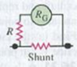
The resistance of the coil of a pivoted coil galvanometer is 9.36 Ω, and a current of 0.0224 A causes it to deflect full scale. We want to convert this galvanometer to an ammeter reading 20.0 A full scale. The only shunt available has a resistance of 0.0250 Ω. What resistance R must be connected in series with the coil (Fig. E26.36)?
Figure E26.36
Expert Solution & Answer

Learn your wayIncludes step-by-step video

schedule05:10
Students have asked these similar questions
When switch S in Fig. E25.33 is open, the voltmeter V of the battery reads 3.08 V. When the switch is closed, the voltmeter reading drops to 2.97 V, and the ammeter A reads 1.65 A. Find the emf, the internal resistance of the battery, and the circuit resistance R. Assume that the two meters are ideal, so they don’t affect the circuit.
A capacitor charging circuit consists of a battery, an uncharged 20 μF capacitor, and a 5.6 kΩkΩ resistor. At t = 0 ss the switch is closed; 0.15 s later, the current is 0.46 mA . What is the battery's emf?
A series circuit is comprised of a 200VDC battery, a switch, a 1 kΩ resistor and a 10000 µF capacitor.
Initially the switch is open and the capacitor is uncharged.
What is the resistor voltage 29 seconds after the switch is closed?
answer should be in V.
Chapter 26 Solutions
University Physics with Modern Physics (14th Edition)
Ch. 26.1 - Suppose all three of the resistors shown in Fig....Ch. 26.2 - Subtract Eq. (1) from Eq. (2) in Example 26.6. To...Ch. 26.3 - You want to measure the current through and the...Ch. 26.4 - The energy stored in a capacitor is equal to...Ch. 26.5 - To prevent the circuit breaker in Example 26.14...Ch. 26 - In which 120-V light bulb does the filament have...Ch. 26 - Two 120-V light bulbs, one 25-W and one 200-W,...Ch. 26 - You connect a number of identical light bulbs to a...Ch. 26 - In the circuit shown in Fig. Q26.4, three...Ch. 26 - If two resistors R1 and R2 (R2 R1) are connected...
Ch. 26 - If two resistors R1 and R2 (R2 R1) are connected...Ch. 26 - A battery with no internal resistance is connected...Ch. 26 - A resistor consists of three identical metal...Ch. 26 - A light bulb is connected in the circuit shown in...Ch. 26 - A real battery, having nonnegligible internal...Ch. 26 - If the battery in Discussion Question Q26.10 is...Ch. 26 - Consider the circuit shown in Fig. Q26.12. What...Ch. 26 - Is it possible to connect resistors together in a...Ch. 26 - The battery in the circuit shown in Fig. Q26.14...Ch. 26 - In a two-cell flashlight, the batteries are...Ch. 26 - Identical light bulbs A, B, and C are connected as...Ch. 26 - The emf of a flashlight battery is roughly...Ch. 26 - Will the capacitors in the circuits shown in Fig....Ch. 26 - Verify that the time constant RC has units of...Ch. 26 - For very large resistances it is easy to construct...Ch. 26 - When a capacitor, battery, and resistor are...Ch. 26 - A uniform wire of resistance R is cut into three...Ch. 26 - A machine part has a resistor X protruding from an...Ch. 26 - A resistor with R1 = 25.0 is connected to a...Ch. 26 - A 42- resistor and a 20- resistor are connected in...Ch. 26 - A triangular array of resistors is shown in Fig....Ch. 26 - For the circuit shown in Fig. E26.6 both meters...Ch. 26 - For the circuit shown in Fig. E26.7 find the...Ch. 26 - Three resistors having resistances of 1.60 , 2.40...Ch. 26 - Now the three resistors of Exercise 26.8 are...Ch. 26 - Power Rating of a Resistor. The power rating of a...Ch. 26 - In Fig. E26.11, R1, = 3.00 , R2 = 6.00 , and R3=...Ch. 26 - In Fig. E26.11 the battery has emf 35.0 V and...Ch. 26 - Compute the equivalent resistance of the network...Ch. 26 - Compute the equivalent resistance of the network...Ch. 26 - In the circuit of Fig. E26.15, each resistor...Ch. 26 - Consider the circuit shown in Fig. E26.16. The...Ch. 26 - In the circuit shown in Fig. E26.17, the voltage...Ch. 26 - In the circuit shown in Fig. E26.18, = 36.0 V,...Ch. 26 - CP In the circuit in Fig. E26.19, a 20.0- resistor...Ch. 26 - In the circuit shown in Fig. E26.20, the rate at...Ch. 26 - Light Bulbs in Series and in Parallel. Two light...Ch. 26 - Light Bulbs in Series. A 60-W, 120-V light bulb...Ch. 26 - In the circuit shown in Fig. E26.23, ammeter A1...Ch. 26 - The batteries shown in the circuit in Fig. E26.24...Ch. 26 - In the circuit shown in Fig. E26.25 find (a) the...Ch. 26 - Find the emfs 1 and 2 in the circuit of Fig....Ch. 26 - In the circuit shown in Fig. E26.27, find (a) the...Ch. 26 - In the circuit shown in Fig. E26.28, find (a) the...Ch. 26 - The 10.00-V battery in Fig. E26.28 is removed from...Ch. 26 - The 5.00-V battery in Fig. E26.28 is removed from...Ch. 26 - In the circuit shown in Fig. E26.31 the batteries...Ch. 26 - In the circuit shown in Fig. E26.32 both batteries...Ch. 26 - In the circuit shown in Fig. E26.33 all meters are...Ch. 26 - In the circuit shown in Fig. E26.34, the 6.0-...Ch. 26 - The resistance of a galvanometer coil is 25.0 ,...Ch. 26 - The resistance of the coil of a pivoted coil...Ch. 26 - A circuit consists of a series combination of...Ch. 26 - A galvanometer having a resistance of 25.0 has a...Ch. 26 - A capacitor is charged to a potential of 12.0 V...Ch. 26 - You connect a battery, resistor, and capacitor as...Ch. 26 - A 4.60-F capacitor that is initially uncharged is...Ch. 26 - You connect a battery, resistor, and capacitor as...Ch. 26 - CP In the circuit shown in Fig. E26.43 both...Ch. 26 - A 12.4-F capacitor is connected through a 0.895-M...Ch. 26 - An emf source with = 120 V, a resistor with R =...Ch. 26 - A resistor and a capacitor are connected in series...Ch. 26 - CP In the circuit shown in Fig. E26.47 each...Ch. 26 - A 1.50-F capacitor is charging through a 12.0-...Ch. 26 - In the circuit in Fig. E26.49 the capacitors are...Ch. 26 - A 12.0-F capacitor is charged to a potential of...Ch. 26 - In the circuit shown in Fig. E26.51, C = 5.90 F, ...Ch. 26 - Prob. 26.52ECh. 26 - A 1500-W electric beater is plugged into the...Ch. 26 - In Fig. P26.54, the battery has negligible...Ch. 26 - The two identical light bulbs in Example 26.2...Ch. 26 - Each of the three resistors in Fig. P26.56 has a...Ch. 26 - (a) Find the potential of point a with respect to...Ch. 26 - CP For the circuit shown in Fig. P26.58 a 20.0-...Ch. 26 - Calculate the three currents I1, I2, and I3...Ch. 26 - What must the emf in Fig. P26.60 be in order for...Ch. 26 - Find the current through each of the three...Ch. 26 - (a) Find the current through the battery and each...Ch. 26 - Consider the circuit shown in Fig. P26.63. (a)...Ch. 26 - In the circuit shown in Fig. P26.64, = 24.0 V,...Ch. 26 - In the circuit shown in Fig. P26.65, the current...Ch. 26 - In the circuit shown in Fig. P26.66 all the...Ch. 26 - Figure P26.67 employs a convention often used in...Ch. 26 - Three identical resistors are connected in series....Ch. 26 - A resistor R1 consumes electrical power P1 when...Ch. 26 - The capacitor in Fig. F26.70 is initially...Ch. 26 - A 2.00-F capacitor that is initially uncharged is...Ch. 26 - A 6.00-F capacitor that is initially uncharged is...Ch. 26 - Point a in Fig. P26.73 is maintained at a constant...Ch. 26 - The Wheatstone Bridge. The circuit shown in Fig....Ch. 26 - (See Problem 26.67.) (a) What is the potential of...Ch. 26 - A 2.36-F capacitor that is initially uncharged is...Ch. 26 - A 224- resistor and a 589- resistor are connected...Ch. 26 - A resistor with R = 850 is connected to the...Ch. 26 - A capacitor that is initially uncharged is...Ch. 26 - DATA You set up the circuit shown in Fig. 26.22a,...Ch. 26 - DATA You set up the circuit shown in Fig. 26.20....Ch. 26 - DATA The electronics supply company where you work...Ch. 26 - An Infinite Network. As shown in Fig. P26.83, a...Ch. 26 - Suppose a resistor R lies along each edge of a...Ch. 26 - BIO Attenuator Chains and Axons. The infinite...Ch. 26 - Assume that a typical open ion channel spanning an...Ch. 26 - In a simple model of an axon conducting a nerve...Ch. 26 - Cell membranes across a wide variety of organisms...
Additional Science Textbook Solutions
Find more solutions based on key concepts
6. If the magnitude of the magnetic force on a proton is F when it is moving at 15.0° with respect to the field...
College Physics (10th Edition)
1. In uniform circular motion, which of the following are constant: speed, velocity, angular velocity, centripe...
Physics for Scientists and Engineers: A Strategic Approach, Vol. 1 (Chs 1-21) (4th Edition)
22. Chris is holding two softballs while standing on a balcony. She throws ball 1 straight up in the air and, a...
College Physics: A Strategic Approach (3rd Edition)
Choose the best answer to each of the following. Explain your reasoning. a photograph of a cluster of galaxies ...
Cosmic Perspective Fundamentals
The pV-diagram of the Carnot cycle.
Sears And Zemansky's University Physics With Modern Physics
Knowledge Booster


Learn more about
Need a deep-dive on the concept behind this application? Look no further. Learn more about this topic, physics and related others by exploring similar questions and additional content below.Similar questions
- Consider a series RC circuit as in Figure P28.38 for which R = 1.00 M, C = 5.00 F, and = 30.0 V. Find (a) the time constant of the circuit and (b) the maximum charge on the capacitor after the switch is thrown closed. (c) Find the current in the resistor 10.0 s after the switch is closed.arrow_forwardA battery with = 6.00 V and no internal resistance supplies current to the circuit shown in Figure P27.9. When the double-throw switch S is open as shown in the figure, the current in the battery is 1.00 mA. When the switch is closed in position a, the current in the battery is 1.20 mA. When the switch is closed in position b, the current in the battery is 2.00 mA. Find the resistances (a) R1, (b) R2, and (c) R3. Figure P27.9 Problems 9 and 10.arrow_forwardIn the circuit of Figure P27.25, the switch S has been open for a long time. It is then suddenly closed. Take = 10.0 V, R1 = 50.0 k, R2 = 100 k, and C = 10.0 F. Determine the time constant (a) before the switch is closed and (b) after the switch is closed. (c) Let the switch be closed at t = 0. Determine the current in the switch as a function of time. Figure P27.25 Problems 25 and 26.arrow_forward
- A battery with emf ε and no internal resistance supplies current to the circuit shown in Figure P27.9.When thee double-throw switch S is ope as shown in the figure,the current in the battery is Io.when the switch is closed in position a the current in the battery is Ia.when the switch is closed in position b,the current in the battery is Ib.Find the resistance (a) R1,(b) R2 and (c) R3 Figure P27.9 problems 9 and 10arrow_forwardYour answer is partially correct. In the figure the current in resistance 6 is ig = 1.44 A and the resistances are R1 = R2 = R3 = 2.49 Q, R4 = 16.2 Q, R5 = 8.420, and Ré = 3.32 Q. What is the emf of the ideal battery? R R2 R4 16 Number i 44.4 Units Varrow_forwardA capacitor with a capacitance of 3.5 μF is initially uncharged. It is connected in series with a switch of negligible resistance, a resistor with a resistance of 19.5 kΩ, and a battery that has a potential difference of 155 V. 1. Immediately after the switch is closed, what is the current, in amperes, through the resistor? 2. Find an expression for the time after the switch is closed when the current in the resistor equals half its maximum value. 3. What is the charge Q, in microcoulombs, on the capacitor when the current in the resistor equals one half its maximum value.arrow_forward
- A battery has emf E and internal resistance r = 2.00 Ω. A 12.0 Ω resistor is connected to the battery, and the resistor consumes electrical power at a rate of 96.0 J/ What is the emf of the battery?arrow_forward25.54. In the circuit shown in Fig. P25.54, R is a variable resistor whose value ranges from 0 to co, and a and b are the terminals of a battery that has an emf E = 15.0V and an internal resistance of 4.00 2. The ammeter and voltmeter are idealized meters. As R varies over its full range of values, what will be the largest and smallest readings of (a) the voltmeter and (b) the ammeter? (c) Sketch qualita- tive graphs of the readings of both meters as functions of R. Figure P25.54 Rarrow_forwardAn initially uncharged 4.93 x 10⁻⁶ F capacitor and a 7070 2 resistor are connected in series to a 1.50 V battery that has negligible internal resistance. What is the initial current I, in the circuit? Io = A Calculate the circuit's time constant t. T = S How much time t must elapse from the closing of the circuit for the current to decrease to 3.07% of its initial value? t = Sarrow_forward
- A 15.00 Ω resistor and 7.00 Ω resistor are connected in parallel to an emf source. A current of 1.50 A is in the 7.00 Ω resistor. What is the potential difference across the source?arrow_forward852 9,2 2452 3052 The power dissipated in the 5 Ohms resistor is 80 W. A. The circuit's total current is A. B. The circuit's total voltage is V. C. The power dissipated in the 30 Ohms resistor is W. Round all answers to whole numbers.arrow_forwardFour resistors are combined in a circuit along with a battery and an ammeter. The values of the resistors are R1 = 5 Ω, R2 = 5 Ω, R3 = 10 Ω, and R4 = 20 Ω. If the current through the ammeter is 2.6 A and the voltage of the battery is 50 V, what is the configuration of the resistors?arrow_forward
arrow_back_ios
SEE MORE QUESTIONS
arrow_forward_ios
Recommended textbooks for you
 Physics for Scientists and Engineers: Foundations...PhysicsISBN:9781133939146Author:Katz, Debora M.Publisher:Cengage Learning
 Principles of Physics: A Calculus-Based TextPhysicsISBN:9781133104261Author:Raymond A. Serway, John W. JewettPublisher:Cengage Learning
 Physics for Scientists and Engineers, Technology ...PhysicsISBN:9781305116399Author:Raymond A. Serway, John W. JewettPublisher:Cengage Learning
 Physics for Scientists and Engineers with Modern ...PhysicsISBN:9781337553292Author:Raymond A. Serway, John W. JewettPublisher:Cengage Learning
 Physics for Scientists and EngineersPhysicsISBN:9781337553278Author:Raymond A. Serway, John W. JewettPublisher:Cengage Learning
Physics for Scientists and Engineers: Foundations...
Physics
ISBN:9781133939146
Author:Katz, Debora M.
Publisher:Cengage Learning
Principles of Physics: A Calculus-Based Text
Physics
ISBN:9781133104261
Author:Raymond A. Serway, John W. Jewett
Publisher:Cengage Learning
Physics for Scientists and Engineers, Technology ...
Physics
ISBN:9781305116399
Author:Raymond A. Serway, John W. Jewett
Publisher:Cengage Learning
Physics for Scientists and Engineers with Modern ...
Physics
ISBN:9781337553292
Author:Raymond A. Serway, John W. Jewett
Publisher:Cengage Learning
Physics for Scientists and Engineers
Physics
ISBN:9781337553278
Author:Raymond A. Serway, John W. Jewett
Publisher:Cengage Learning
DC Series circuits explained - The basics working principle; Author: The Engineering Mindset;https://www.youtube.com/watch?v=VV6tZ3Aqfuc;License: Standard YouTube License, CC-BY