
Essential University Physics
4th Edition
ISBN: 9780134988566
Author: Wolfson, Richard
Publisher: Pearson Education,
expand_more
expand_more
format_list_bulleted
Videos
Textbook Question
Chapter 25.2, Problem 25.2GI
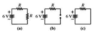
Rank front highest to lowest the voltages across the identical resistors R at the top of each circuit shown, and give the actual voltage for each. In (a) the second resistor has the same resistance R, and in (b) the gap is an open circuit (infinite resistance).
Expert Solution & Answer
Want to see the full answer?
Check out a sample textbook solution
Students have asked these similar questions
For the following circuit in the figure
below, find the power ( in units of
Watt) delivered to the 2R-resistor
when ε = 15.2 V and R = 3.0 Q?
Compute for the voltage Vac in the circuit shown below.
In the circuit shown in the figure (Figure 1), the 6.0 ΩΩ resistor is consuming energy at a rate of 21 J/sJ/s when the current through it flows as shown.
What are the polarity and emf of the battery EE, assuming it has negligible internal resistance?
Express your answer with the appropriate units. Enter positive value if the polarity of the battery is the same as shown the figure and negative value in another case.
Chapter 25 Solutions
Essential University Physics
Ch. 25.1 - The figure shows three circuits. Which are...Ch. 25.2 - Rank front highest to lowest the voltages across...Ch. 25.2 - The figure shows all four possible combinations of...Ch. 25.2 - The figure shows a circuit with three identical...Ch. 25.3 - Which circuit(s) cannot be analyzed using series...Ch. 25.4 - All resistors in the figure have the same value...Ch. 25.5 - A capacitor is charged to 12 V and then connected...Ch. 25 - Are household electrical outlets connected in...Ch. 25 - Can the voltage across a batterys terminals differ...Ch. 25 - Can the voltage across a batterys terminals he...
Ch. 25 - When the switch in Fig. 25.25 is open, whats the...Ch. 25 - Two identical resistors in series dissipate equal...Ch. 25 - When a large electric load such as a washing...Ch. 25 - How would you connect a pair of equal resistors...Ch. 25 - You have a battery whose voltage and internal...Ch. 25 - A student whos confused about voltage and current...Ch. 25 - A student whos confused about voltage and current...Ch. 25 - Sketch a circuit diagram for a circuit that...Ch. 25 - Sketch a diagram for a circuit consisting of two...Ch. 25 - Resistors R1 and R2 are in series, and the series...Ch. 25 - Whats the emf of a battery that delivers 27 J of...Ch. 25 - A 1.5-V battery stores 4.5 kJ of energy. How long...Ch. 25 - If you accidentally leave your car headlights...Ch. 25 - A 47-k resistor and a 39-k resistor are in...Ch. 25 - What resistance should you place in parallel with...Ch. 25 - A defective starter motor draws 285 A from a car's...Ch. 25 - Find the internal resistance of the battery in...Ch. 25 - When a 9-V battery is temporarily short-circuited,...Ch. 25 - You have a 1.0-, a 2.0-, and a 3.0- resistor. What...Ch. 25 - Find all three currents in the circuit of Fig....Ch. 25 - Prob. 24ECh. 25 - Find all three currents in the circuit of Fig....Ch. 25 - Prob. 26ECh. 25 - An ammeter with 100- resistance is inserted in the...Ch. 25 - A new mechanic foolishly connects an ammeter with...Ch. 25 - Show that the quantity RC has the units of time...Ch. 25 - If capacitance is in F, what will he the units of...Ch. 25 - Show that a capacitor is charged to approximately...Ch. 25 - An uncharged 10-F capacitor and a 470-k resistor...Ch. 25 - Find an expression for the voltage across the...Ch. 25 - Rework Example 25.3. changing the 4.0- Ω resistor...Ch. 25 - Example 25.3: In the circuit of Example 25.3, take...Ch. 25 - Example 25.3: In Fig. 25.27, take R1 = R2 = 33.0 Ω...Ch. 25 - Example 25.3 In Fig. 25.27, take R1 = 220 Ω, R2 =...Ch. 25 - A professional-grade camera flash gets its energy...Ch. 25 - You're reengieering the camera flash of the...Ch. 25 - Defibrillators restore normal heart rhythm by...Ch. 25 - Example 25.5: You’re designing a defibrillator as...Ch. 25 - In Fig. 25.28, all resistors have the same value,...Ch. 25 - In Fig. 25.28, take all resistors to be 1 k Find...Ch. 25 - Three 1.5-V batteries, with internal resistances...Ch. 25 - Prob. 45PCh. 25 - You company is designing a battery-based backup...Ch. 25 - In the circuit of Fig. 25.30, find (a) the current...Ch. 25 - In Fig. 25.30, how much power is dissipated in the...Ch. 25 - Whats the ammeter reading in Fig. 25.31? FIGURE...Ch. 25 - Find all three currents in the circuit of Fig....Ch. 25 - In Example 25.4. ε2, is taken to be +9 V in the...Ch. 25 - The voltage across the 30-k resistor in Fig. 25.33...Ch. 25 - In Fig. 25.34, what are the meter readings when an...Ch. 25 - Prob. 55PCh. 25 - The voltage across a charging capacitor in an RC...Ch. 25 - Youre designing an external defibrillator that...Ch. 25 - A capacitor is charged until it holds 5.0 J of...Ch. 25 - A capacitor is charged until it holds 5.0 J of...Ch. 25 - In Fig. 25.35 the 2.0-F capacitor is charged to...Ch. 25 - For the circuit of Example 25.6, take = 100 V,...Ch. 25 - In Fig. 25.36, the switch is initially open and...Ch. 25 - Prob. 63PCh. 25 - An ammeter with resistance 1.42 is connected...Ch. 25 - In Fig. 25.37, take 1 = 12.0 V, 2 = 6.00 V, 3 =...Ch. 25 - With all values except 2 as given in the preceding...Ch. 25 - The voltage on a charged capacitor is monitored...Ch. 25 - Find the resistance needed in an RC circuit to...Ch. 25 - Suppose the currents into and out of a circuit...Ch. 25 - Show that a battery delivers the most power when...Ch. 25 - Youre writing the instruction manual for a stereo...Ch. 25 - Show that only half the total energy drawn from a...Ch. 25 - Find the equivalent resistance between A and B for...Ch. 25 - Prob. 74PCh. 25 - Obtain an expression for the rate of increase...Ch. 25 - The circuit in Fig. 25.39 extends forever to the...Ch. 25 - Figure 25.40 on the next page shows the voltage...Ch. 25 - Figure 25.41 shows a portion of a circuit used to...Ch. 25 - An electrochemical impulse traveling along the...Ch. 25 - In Fig. 25.27, take R1 = 47 Ω and R2 = 150 Ω....Ch. 25 - Write the node and loop equations for the circuit...Ch. 25 - Youre about to purchase a battery. Normally,...Ch. 25 - In the circuit of Fig. 25.42 the switch is...Ch. 25 - BIO Stray voltage is a serious problem on dairy...Ch. 25 - BIO Stray voltage is a serious problem on dairy...Ch. 25 - BIO Stray voltage is a serious problem on dairy...Ch. 25 - BIO Stray voltage is a serious problem on dairy...
Additional Science Textbook Solutions
Find more solutions based on key concepts
Consider a uranium nucleus to be sphere of radius R=7.41015 m with a charge of 92e distributed uniformly throug...
University Physics Volume 2
25.1 and 25.2 Polarization of waves and Discovery of electromagnetic waves One dipole antenna points in the x-d...
College Physics
The height of a certain hill (in feet) is given by , where y is the distance (in miles) north, x the distance e...
Introduction to Electrodynamics
Whether the area of shaded region corresponding to window 1 greater than, less than or equal to the area of the...
Physics (5th Edition)
The figure shows snapshots of two waves propagating with the same speed. Which has the greater (1) amplitude, (...
Essential University Physics: Volume 1 (3rd Edition)
19. Sandy and Chris stand on the edge of a cliff and throw identical mass rocks at the same speed. Sandy throws...
College Physics: A Strategic Approach (4th Edition)
Knowledge Booster


Learn more about
Need a deep-dive on the concept behind this application? Look no further. Learn more about this topic, physics and related others by exploring similar questions and additional content below.Similar questions
- Two 23.0 cm long parallel wires in the diagram above are separated by 4.50 mm. For what value of the resistor R (in ohm) will the force between the two wires be 2.50 x 10⁻⁵ N?arrow_forwardGiven the circuit diagram belowand assuming that the emf(ε=12V) Find:(a) the total resistance(b) the total current in the circuit(c) the current in each resistor (d) the potential difference acrosseach resistor (e) the power dissipated by eachresistor (f) the power dissipated by theentire circuitarrow_forwardIn the figure, the total resistance is 10kΩ, and the battery's emf is 20.0 V.If the time constant is measure to be 20.0 μseconds, calculate the time it takes for the voltage across the resistor to reach 15.0 V after the switch is closed.arrow_forward
- Consider the circuit diagram depicted in the figure. If the current through the top branch is I2 = 0.81 A, what is the current through the bottom, I3, in amps?arrow_forwardTwo fixed type resistors, 5 ohms and 7,5 ohms are connected in series. 3. If a 12 volt battery is supplied to the series connection, solve for the amount of power dissipated by the 5 ohm resistor. 4. If a 12 volt battery is supplied to the series connection, compute for the total power used by the circuit.arrow_forwardIn the given figure, six resistors are connected in combination of series and parallel. Given the values of each resitance find the following and show your solution. a) Total resistance b) Total currentarrow_forward
- An electronic apparatus may have large capacitors at high voltage in the power supply section, presenting a shock hazard even when the apparatus is switched off. A “bleeder resistor” is therefore placed across such a capacitor, as shown schematically in Figure, to bleed the charge from it after the apparatus is off. Why must the bleeder resistance be much greater than theeffective resistance of the rest of the circuit? How does this affect the time constant for discharging the capacitor?arrow_forwardWhen a voltmeter is connected across the terminals of a resistor, what usually happens to the potential difference across the resistor? What does the answer to this question suggests concerning a desirable design for voltmeters?arrow_forwardIn the circuit the right hand LED lights up,mark the poles with + and -?arrow_forward
- Find the value of I (current) in the circuit component shown in the figure.arrow_forwardCompute for the current i3 in the circuit shown belowarrow_forwardThe circuit shown in the diagram consists of 10-volt battery, a 47-ohm resistor, and 0.375-farad capacitor, connected as shown. Suppose the switch had been in Position 1 for a long time and is just being moved to Position 2. Let t = 0 at the instant the switch is placed in Position 2. At what time t will the voltage across the capacitor equal 5 volts?arrow_forward
arrow_back_ios
arrow_forward_ios
Recommended textbooks for you
 Glencoe Physics: Principles and Problems, Student...PhysicsISBN:9780078807213Author:Paul W. ZitzewitzPublisher:Glencoe/McGraw-Hill
 Principles of Physics: A Calculus-Based TextPhysicsISBN:9781133104261Author:Raymond A. Serway, John W. JewettPublisher:Cengage Learning
 An Introduction to Physical SciencePhysicsISBN:9781305079137Author:James Shipman, Jerry D. Wilson, Charles A. Higgins, Omar TorresPublisher:Cengage Learning
Glencoe Physics: Principles and Problems, Student...
Physics
ISBN:9780078807213
Author:Paul W. Zitzewitz
Publisher:Glencoe/McGraw-Hill
Principles of Physics: A Calculus-Based Text
Physics
ISBN:9781133104261
Author:Raymond A. Serway, John W. Jewett
Publisher:Cengage Learning
An Introduction to Physical Science
Physics
ISBN:9781305079137
Author:James Shipman, Jerry D. Wilson, Charles A. Higgins, Omar Torres
Publisher:Cengage Learning
How To Solve Any Resistors In Series and Parallel Combination Circuit Problems in Physics; Author: The Organic Chemistry Tutor;https://www.youtube.com/watch?v=eFlJy0cPbsY;License: Standard YouTube License, CC-BY