
Essential University Physics
4th Edition
ISBN: 9780134988566
Author: Wolfson, Richard
Publisher: Pearson Education,
expand_more
expand_more
format_list_bulleted
Videos
Textbook Question
Chapter 25, Problem 78P
Figure 25.41 shows a portion of a circuit used to model muscle cells and neurons. All resistors have the same value R = 1.5 MΩ, and the emfs are ℰ1 = 75 mV, ℰ2 = 45 mV, and ℰ3 = 20 mV. Find the current through ℰ3, including its direction.
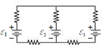
FIGURE 25.41 Problems 76 and 77
Expert Solution & Answer
Want to see the full answer?
Check out a sample textbook solution
Students have asked these similar questions
A cell of em.f. 2V and external
resistance 0.5 Q is connected across a resistor
(R). The current that flows is same as that,
when a cell of e.m.f. 1.5 V and external
resistance 0.3 Q is connected across the same
resistor. Then
R=03Q
(b) R=0.60
R=05Q
(d) R=0.75 92
The figure shows an ideal battery of emf 8 = 28 V, a resistor of resistance R = 6.6 02, and an uncharged capacitor of capacitance C = 5.7
μF. After switch S is closed, what is the current through the resistor when the charge on the capacitor is 9.2 µC?
Number i
Units
HE
Sm
R
<
C
The figure shows an ideal battery of emf € = 13 V, a resistor
of resistance R = 6.3 M2, and an uncharged capacitor of
capacitance C = 6.3 μF. After switch S is closed, what is
the current through the resistor when the charge on the
capacitor is 9.5 μC?
4
R
Chapter 25 Solutions
Essential University Physics
Ch. 25.1 - The figure shows three circuits. Which are...Ch. 25.2 - Rank front highest to lowest the voltages across...Ch. 25.2 - The figure shows all four possible combinations of...Ch. 25.2 - The figure shows a circuit with three identical...Ch. 25.3 - Which circuit(s) cannot be analyzed using series...Ch. 25.4 - All resistors in the figure have the same value...Ch. 25.5 - A capacitor is charged to 12 V and then connected...Ch. 25 - Are household electrical outlets connected in...Ch. 25 - Can the voltage across a batterys terminals differ...Ch. 25 - Can the voltage across a batterys terminals he...
Ch. 25 - When the switch in Fig. 25.25 is open, whats the...Ch. 25 - Two identical resistors in series dissipate equal...Ch. 25 - When a large electric load such as a washing...Ch. 25 - How would you connect a pair of equal resistors...Ch. 25 - You have a battery whose voltage and internal...Ch. 25 - A student whos confused about voltage and current...Ch. 25 - A student whos confused about voltage and current...Ch. 25 - Sketch a circuit diagram for a circuit that...Ch. 25 - Sketch a diagram for a circuit consisting of two...Ch. 25 - Resistors R1 and R2 are in series, and the series...Ch. 25 - Whats the emf of a battery that delivers 27 J of...Ch. 25 - A 1.5-V battery stores 4.5 kJ of energy. How long...Ch. 25 - If you accidentally leave your car headlights...Ch. 25 - A 47-k resistor and a 39-k resistor are in...Ch. 25 - What resistance should you place in parallel with...Ch. 25 - A defective starter motor draws 285 A from a car's...Ch. 25 - Find the internal resistance of the battery in...Ch. 25 - When a 9-V battery is temporarily short-circuited,...Ch. 25 - You have a 1.0-, a 2.0-, and a 3.0- resistor. What...Ch. 25 - Find all three currents in the circuit of Fig....Ch. 25 - Prob. 24ECh. 25 - Find all three currents in the circuit of Fig....Ch. 25 - Prob. 26ECh. 25 - An ammeter with 100- resistance is inserted in the...Ch. 25 - A new mechanic foolishly connects an ammeter with...Ch. 25 - Show that the quantity RC has the units of time...Ch. 25 - If capacitance is in F, what will he the units of...Ch. 25 - Show that a capacitor is charged to approximately...Ch. 25 - An uncharged 10-F capacitor and a 470-k resistor...Ch. 25 - Find an expression for the voltage across the...Ch. 25 - Rework Example 25.3. changing the 4.0- Ω resistor...Ch. 25 - Example 25.3: In the circuit of Example 25.3, take...Ch. 25 - Example 25.3: In Fig. 25.27, take R1 = R2 = 33.0 Ω...Ch. 25 - Example 25.3 In Fig. 25.27, take R1 = 220 Ω, R2 =...Ch. 25 - A professional-grade camera flash gets its energy...Ch. 25 - You're reengieering the camera flash of the...Ch. 25 - Defibrillators restore normal heart rhythm by...Ch. 25 - Example 25.5: You’re designing a defibrillator as...Ch. 25 - In Fig. 25.28, all resistors have the same value,...Ch. 25 - In Fig. 25.28, take all resistors to be 1 k Find...Ch. 25 - Three 1.5-V batteries, with internal resistances...Ch. 25 - Prob. 45PCh. 25 - You company is designing a battery-based backup...Ch. 25 - In the circuit of Fig. 25.30, find (a) the current...Ch. 25 - In Fig. 25.30, how much power is dissipated in the...Ch. 25 - Whats the ammeter reading in Fig. 25.31? FIGURE...Ch. 25 - Find all three currents in the circuit of Fig....Ch. 25 - In Example 25.4. ε2, is taken to be +9 V in the...Ch. 25 - The voltage across the 30-k resistor in Fig. 25.33...Ch. 25 - In Fig. 25.34, what are the meter readings when an...Ch. 25 - Prob. 55PCh. 25 - The voltage across a charging capacitor in an RC...Ch. 25 - Youre designing an external defibrillator that...Ch. 25 - A capacitor is charged until it holds 5.0 J of...Ch. 25 - A capacitor is charged until it holds 5.0 J of...Ch. 25 - In Fig. 25.35 the 2.0-F capacitor is charged to...Ch. 25 - For the circuit of Example 25.6, take = 100 V,...Ch. 25 - In Fig. 25.36, the switch is initially open and...Ch. 25 - Prob. 63PCh. 25 - An ammeter with resistance 1.42 is connected...Ch. 25 - In Fig. 25.37, take 1 = 12.0 V, 2 = 6.00 V, 3 =...Ch. 25 - With all values except 2 as given in the preceding...Ch. 25 - The voltage on a charged capacitor is monitored...Ch. 25 - Find the resistance needed in an RC circuit to...Ch. 25 - Suppose the currents into and out of a circuit...Ch. 25 - Show that a battery delivers the most power when...Ch. 25 - Youre writing the instruction manual for a stereo...Ch. 25 - Show that only half the total energy drawn from a...Ch. 25 - Find the equivalent resistance between A and B for...Ch. 25 - Prob. 74PCh. 25 - Obtain an expression for the rate of increase...Ch. 25 - The circuit in Fig. 25.39 extends forever to the...Ch. 25 - Figure 25.40 on the next page shows the voltage...Ch. 25 - Figure 25.41 shows a portion of a circuit used to...Ch. 25 - An electrochemical impulse traveling along the...Ch. 25 - In Fig. 25.27, take R1 = 47 Ω and R2 = 150 Ω....Ch. 25 - Write the node and loop equations for the circuit...Ch. 25 - Youre about to purchase a battery. Normally,...Ch. 25 - In the circuit of Fig. 25.42 the switch is...Ch. 25 - BIO Stray voltage is a serious problem on dairy...Ch. 25 - BIO Stray voltage is a serious problem on dairy...Ch. 25 - BIO Stray voltage is a serious problem on dairy...Ch. 25 - BIO Stray voltage is a serious problem on dairy...
Additional Science Textbook Solutions
Find more solutions based on key concepts
The speed of the person sitting on the chair relative to the chair and relative to Earth.
Conceptual Physics (12th Edition)
A 500-kg dragster accelerates from rest to a final speed of 110 m/s in 400 m (about a quarter of a mile) and en...
University Physics Volume 1
Human moment of inertia. The moment of inertia of the human body about an axis through its center of mass is im...
College Physics (10th Edition)
The direction of flow of current in loop to produce zero magnetic field.
Physics (5th Edition)
The pV-diagram of the Carnot cycle.
Sears And Zemansky's University Physics With Modern Physics
Knowledge Booster


Learn more about
Need a deep-dive on the concept behind this application? Look no further. Learn more about this topic, physics and related others by exploring similar questions and additional content below.Similar questions
- Consider a series RC circuit as in Figure P28.38 for which R = 1.00 M, C = 5.00 F, and = 30.0 V. Find (a) the time constant of the circuit and (b) the maximum charge on the capacitor after the switch is thrown closed. (c) Find the current in the resistor 10.0 s after the switch is closed.arrow_forwardA 12.0-V emf automobile battery has a terminal voltage of 16.0 V when being charged by a current of 10.0 A. (a) What is the battery’s internal resistance? (b) What power is dissipated inside the battery? (c) At what rate (in °C/min ) will its temperature increase if its mass is 20.0 kg and it has a specific heat of 0.300 kcal/kg • °C, assuming no heat escapes?arrow_forwardA 10.00-meter long wire cable that is made of copper has a resistance of 0.051 ohms, (a) What is the weight if the wire was made of copper? (b) What is the weight of a 10.00-meter-long wire of the same gauge made of aluminum? (c)What is the resistance of the aluminum wire? The density of copper is 8960 kg/m3 and the density of aluminum is 2760 kg/m3.arrow_forward
- A solar cell generates a potential difference of 0.17 V when a 550 resistor is connected across it, and a potential difference of 0.24 V when a 970 resistor is substituted. What are the (a) internal resistance and (b) emf of the solar cell? (c) The area of the cell is 1.2 cm² and the rate per unit area at which it receives energy from light is 4.9 mW/cm². What is the efficiency of the cell for converting light energy to thermal energy in the 970 2 external resistor? (a) Number (b) Number (c) Number i Units Units Units Ω V perarrow_forwardConsider the circuit shown in Figure. The emf source has negligible internal resistance. The resistors have resistances R1= 6Ω and R2= 4Ω. The capacitor has capacitance C=9 μF. When the capacitor is fully charged, the magnitude of the charge on its plates is Q=36. Calculate the emf ε.arrow_forwardA circuit made up of 6 resistors is shown in the figure, with resistances R1 =11 Q, R2 = 45 N, R3 = 45 Q, R4 = 52 Q, R5 = 89 N, and R6= 38 Q. The total current going through the circuit is I= 3.5 A. R, RA a R R2 R. b 1. Calculate the value of AV, in volts.arrow_forward
- In the figure &1 = 5.96 V, E2 = 10.2 V, R1 = 101 0, R2 = 193 0, and R3 = 270 0. One point of the circuit is grounded (V = 0). What are the (a) size and (b) direction (up or down) of the current through resistance 1, the (c) size and (d) direction (left or right) of the current through resistance 2, and the (e) size and (f) direction of the current through resistance 3? (g) What is the electric potential at point A? A R2 R3 R1 (a) Number i Units (b) (c) Number i Units (d) (e) Number i Units (f) (g) Number i Units >arrow_forwardA 400 µF capacitor is connected through a resistor to a battery. Find (a) the resistance R and (b) the emf of the battery if the time constant of the circuit is 0.5 s and the maximum charge on the capacitor is 0.024 C. O a. R = 1350 0, e = 80 V O b. R = 1250 0, E = 60 V O C. R = 1200 Q, e = 80 V O d. R = 1150 Q, e = 60 Varrow_forwardA capacitor charging circuit consists of a battery, an uncharged 20 μF capacitor, and a 5.6 kΩkΩ resistor. At t = 0 ss the switch is closed; 0.15 s later, the current is 0.46 mA . What is the battery's emf?arrow_forward
- In (Figure 1), R1R1R_1 = 3.00 ΩΩ, R2R2R_2 = 7.00 ΩΩ, and R3R3R_3 = 4.00 ΩΩ. The battery has negligible internal resistance. The current I2I2 through R2R2 is 3.00 A . What is the emf of the battery? Express your answer with the appropriate units.arrow_forwardChapter 27, Problem 033 GO In the figure the current in resistance 6 is i6 = 1.47 A and the resistances are R₁ = R₂ = R3 = 1.75 2, R4 = 15.0, R5 = 8.83 What is the emf of the ideal battery? 66 E R₁ R₂ R₂ FWM T 8 FWM 8 www R R₁ Chapter 27, Problem 039 GO In the figure two batteries of emf E = 11.0 V and internal resistance r = 0.306 2 are connected in parallel across a resistance R. (a) For what value of R is the dissipation rate in the resistor a maximum? (b) What is that maximum? , and R6 = 3.55 9. 2. www R io Ro 16arrow_forwardThe emf source, ɛ=4.5 V, of the circuit shown in the figure has negligible internal resistance. The resistors have resistances R1=2 Q and R2=4.7 Q. The capacitor has a capacitance C=4.9 µF. Determine the time constant t, in units of microseconds, for charging the capacitor. What is the charge Q on the capacitor in units of microcoulomb?arrow_forward
arrow_back_ios
SEE MORE QUESTIONS
arrow_forward_ios
Recommended textbooks for you
 Principles of Physics: A Calculus-Based TextPhysicsISBN:9781133104261Author:Raymond A. Serway, John W. JewettPublisher:Cengage Learning
 Physics for Scientists and Engineers: Foundations...PhysicsISBN:9781133939146Author:Katz, Debora M.Publisher:Cengage Learning
 Physics for Scientists and Engineers, Technology ...PhysicsISBN:9781305116399Author:Raymond A. Serway, John W. JewettPublisher:Cengage Learning
Principles of Physics: A Calculus-Based Text
Physics
ISBN:9781133104261
Author:Raymond A. Serway, John W. Jewett
Publisher:Cengage Learning
Physics for Scientists and Engineers: Foundations...
Physics
ISBN:9781133939146
Author:Katz, Debora M.
Publisher:Cengage Learning
Physics for Scientists and Engineers, Technology ...
Physics
ISBN:9781305116399
Author:Raymond A. Serway, John W. Jewett
Publisher:Cengage Learning
DC Series circuits explained - The basics working principle; Author: The Engineering Mindset;https://www.youtube.com/watch?v=VV6tZ3Aqfuc;License: Standard YouTube License, CC-BY