Concept explainers
Videos
Referring to Fig. 25-13, what is the equivalent capacitance of the circuit across the 6.0-V battery? What are the voltages across
![Chapter 25, Problem 66SP, 25.66 [II] Referring to Fig. 25-13, what is the equivalent capacitance of the circuit across the](https://content.bartleby.com/tbms-images/9781259587399/Chapter-25/images/87399-25-66sp-question-digital_image95.png)
Fig. 25-13
The equivalent capacitanceacross the
Answer to Problem 66SP
Solution:
Explanation of Solution
Given data:
Refer to the circuit mentioned in the Fig.25-13.
The potential difference of the battery is
Formula used:
Write the expression for equivalent capacitance, when the capacitors are connected in series.
Here,
Write the expression for equivalent capacitance, when the capacitors are connected in parallel.
Write the expression for the charge on the capacitor.
Here,
Write the expression for the energy stored in the system of capacitors.
Here,
Explanation:
Consider the following figure 1.
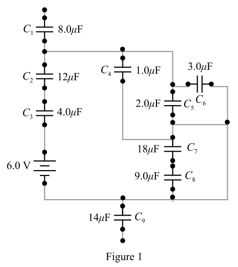
From figure 1, the capacitors
Consider Figure 2, it is a reduced form of figure 1.
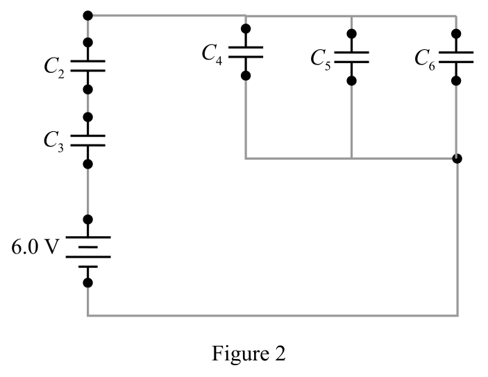
From figure 2, the capacitors
The expression for equivalent capacitance, when the capacitors are connected in parallel is,
Here,
Substitute
The resultant combination
The expression for equivalent capacitance, when the capacitors are connected in series is,
Here,
Substitute
Thus, the equivalent capacitance across the
Calculate the total charge flow in the circuit.
Write the expression for the charge on the capacitor.
Here,
Substitute
If the capacitors are connected in series, then the charge flow across each capacitor is same.
Thus, charge flow across the capacitor
Here,
The expression for the charge across thecapacitor
Here,
Substitute
Solve for
Since the capacitors
Here,
The capacitor
Here,
The charge across the parallel combination
The expression for the charge on the parallel combination
Substitute
Solve for
Since, the capacitors
The voltage across the capacitor
Here,
The expression for a charge on the capacitor
Here,
Substitute
Solve for
The
The expression for the energy stored in the capacitor
Substitute
Conclusion:
The equivalent capacitance across the
Want to see more full solutions like this?
Chapter 25 Solutions
Schaum's Outline of College Physics, Twelfth Edition (Schaum's Outlines)


- Two capacitors, C1 = 18.0 F and C2 = 36.0 F, are connected in series, and a 12.0-V battery is connected across the two capacitors. Find (a) the equivalent capacitance and (b) the energy stored in this equivalent capacitance. (c) Find the energy stored in each individual capacitor. (d) Show that the sum of these two energies is the same as the energy found in part (b). (e) Will this equality always be true, or docs it depend on the number of capacitors and their capacitances? (f) If the same capacitors were connected in parallel, what potential difference would be required across them so that the combination stores the same energy as in part (a)? (g) Which capacitor stores more energy in this situation, C1 or C2?arrow_forwardWhen discharging a capacitor, as discussed in conjunction with Figure 21.39, how long does it take for the voltage on the capacitor to reach zero? Is this a problem?arrow_forwardUsing the exact exponential treatment, find how much time is required to charge an initially uncharged 50-uF (micro-Farad) capacitor through a 75 M-Ohm (mega-ohm) resistor to 60.0% of its final voltage. Group of answer choices a)320 days b)57 minutes c)3.2x10^-2 sec d)4.5 minutesarrow_forward
- Find the equivalent capacitance (in pF) for the combination of capacitors below. C1=141 pF, C2=199 pF, and C3=71 pF.arrow_forwardA 24.0 V battery is connected via switch S to a resistor R = 180 mΩ and two initially uncharged capacitors, C1 = 0.480 μF and C2 = 0.240 μF, as shown in the accompanying circuit diagram. A straight 6.00 m length of nichrome wire with diameter d = 2.50 mm and resistivity 1.1e-6 Ωm is connected in parallel with the resistor and the capacitors. A voltmeter is connected between point X (1.00 m away from one end of the nichrome wire) and point Y, midway between the two capacitors. a)Find the current strength in the nichrome and the resistor after the switch is closed. b)Calculate the charge on each of the fully charged capacitors. c)Determine the steady state reading on the voltmeter.arrow_forwardA 24.0 V battery is connected via switch S to a resistor R = 180 mΩ and two initially uncharged capacitors, C1 = 0.480 μF and C2 = 0.240 μF, as shown in the accompanying circuit diagram. A straight 6.00 m length of nichrome wire with diameter d = 2.50 mm and resistivity 1.1e-6 Ωm is connected in parallel with the resistor and the capacitors. A voltmeter is connected between point X (1.00 m away from one end of the nichrome wire) and point Y, midway between the two capacitors. a)Find the current strength in the nichrome and the resistor 2.88e-8 s after the switch is closed.arrow_forward
- Two capacitors, one C1 = 12.0 mF and the other of unknown capacitance C2, are connected in parallel across a batterywith an emf of 9.00 V. The total energy stored in the two capacitors is 0.0115 J. What is the value of the capacitance C2?arrow_forwardSuppose you wanted to discharge a C = 350 μF capacitor through a R = 350 Ω resistor down to 1.00% of its origional voltage. How much time would be required in seconds?arrow_forwardTwo capacitors, C1 = 19.0 µF and C2 = 40.0 µF, are connected in series, and a 24.0-V battery is connected across the two capacitors. Find the equivalent capacitance, energy stored in this equivalent capacitance, energy stored in each individual capacitor. Show that the sum of these two energies is the same as the energy found stored in equivalent capacitance. Will this equality always be true, or does it depend on the number of capacitors and their capacitances? If the same capacitors were connected in parallel, what potential difference would be required across them so that the combination stores the same energy as in the equivalent capacitance? Which capacitor stores more energy (or are they the same) in this situation, C1or C2?arrow_forward
- A capacitor of 10.0 uF and a resistor of 130 OMEGA are quickly connected in series to a battery of 4.00 V. What is the charge Q on the capacitor 0.00100 s after theconnection is made?arrow_forwardThe capacitance in the curcuit is C = 0.3μF, the total resistance is R=20kQ and the battery emf is 12 V. Determine the time is takes for the charge the capacitor could acquire, to reach 99% of max value.arrow_forwardIn the figure provided, an emf of 9 V is connected to the three capacitors. If C1C1 = 5.70 μF, C2C2 = 2.40 μF and C3C3 = 7.60 μF, what is the charge on C2C2?arrow_forward
 Physics for Scientists and EngineersPhysicsISBN:9781337553278Author:Raymond A. Serway, John W. JewettPublisher:Cengage Learning
 Physics for Scientists and Engineers with Modern ...PhysicsISBN:9781337553292Author:Raymond A. Serway, John W. JewettPublisher:Cengage Learning
 College PhysicsPhysicsISBN:9781938168000Author:Paul Peter Urone, Roger HinrichsPublisher:OpenStax College