
Concept explainers
Videos
(a)
Find the maximum deflection at point C of the cylindrical portions.
(a)
Answer to Problem 107P
The maximum deflection at point C of the cylindrical portions is
Explanation of Solution
Given information:
The cross sectional area AC and BC of each portions is
The modulus of elasticity (E) for portion AC is
The yield stress
The modulus of elasticity (E) for portion CB is
The yield stress
Calculation:
Calculate the displacement at point C to cause yielding of AC using the relation:
Here,
Substitute
Find the corresponding force along AC using the relation as follows:
Substitute
Find the corresponding force along CB using the relation as follows:
Substitute
Sketch the element C as shown in Figure 1.
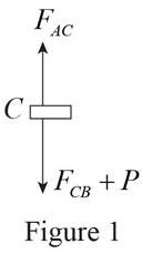
Refer to Figure 1.
Find the value of P using equilibrium element.
Substitute
Since the applied load,
Refer to Figure 1.
Find the force along CB as follows:
Substitute
Determine the deflection at point C using the relation:
Substitute
Thus, the maximum deflection at point C of the cylindrical portions is
(b)
Find the maximum stress for each portion of rod.
(b)
Answer to Problem 107P
The maximum stress of rod AC is
The maximum stress of rod BC is
Explanation of Solution
Calculation:
Refer part a.
The maximum stress of rod AC is
Therefore, the maximum stress of rod AC is
Determine the maximum stress at point BC using the relation:
Substitute
Thus, the maximum stress of rod BC is
(c)
Find the permanent deflection at point C.
(c)
Answer to Problem 107P
The permanent deflection at point C is
Explanation of Solution
Write the expression of deflection and force for unloading as follows:
The value of
Substitute
Determine the deflection using the relation.
Substitute
Find the permanent deflection using the relation:
Substitute
Thus, the permanent deflection at point C is
Want to see more full solutions like this?
Chapter 2 Solutions
EBK MECHANICS OF MATERIALS


- A steel rod of 30 mm diameter is enclosed centrally in a hollow copper tube of external diameter 40 mm and 5 mm thick. The composite bar is then subjected to an axial pull of 45 kN. If the length of the compound rod is 150 mm , and the elasticity moduli are Est = 200 GPa and Ecu = 100 GPa , determine: 1.2.2 The load carried by the rod and that carried by the tubearrow_forward2. The steel structure shown is subjected to the load P=1000 Ib. Assume the cross-sectional area be 0.05 in?, a=10 in, R=5 in, and E=10 ×10ʻ Psi . Determine the distance between the two ends of the structure.arrow_forwardTwo tempered-steel bars, each 316316 in. thick, are bonded to a 1212 -in. mild-steel bar. This composite bar is subjected as shown to a centric axial load of magnitude P. Both steels are elastoplastic with E = 29 × 106 psi and with yield strengths equal to 100 ksi and 50 ksi, respectively, for the tempered and mild steel. Determine the residual stresses in the tempered-steel bars if the load P is gradually increased from zero to 103 kips and then decreased back to zero. The residual stress in the tempered steel bars isarrow_forward
- A steel cylinder is enclosed in a bronze sleeve; both simultaneously support a vertical compressive load of 180 kN which is applied to the assembly through a horizontal bearing plate. The length of the cylinders and sleeves are equal. For the steel cylinder, A= 8000 mm2, E= 200 GPa, and α= 11.7 μm/(m°C). For the bronze sleeve, A= 16 x 103 mm2, E= 83 GPa, and α= 19.0 μm/(m°C). Compute the temperature change that will cause a zero load in the steel.arrow_forward1. The compound bar ABCD has a uniform cross-sectional area of 0.25 in?. When the axial force P is applied, the length of the bar is reduced by 0.018 in. Determine the magnitude of the force P. The moduli of elasticity are 29 x 10° psi for steel and 10 x 106 psi for aluminum. If bronze is used instead of aluminum, determine the length of its reduction if the same force P is applied. The modulus elasticity of bronze is 12 x 10 psi. Indicate reduction by adding the minus (-) sign in your final answer. 18 in. 6 in. 18 in. P P А Steel B C Steel Aluminumarrow_forwardTwo rods, A and B. of equal free length are elastic. Both hang vertically 0.6m apart and support a rigid bar horizontally. The bar remains horizontal when a vertical load of 60 KN is applied to the bar 0.2m from A. If the stress in A is 100 MPa, determine the stress in B and the cross-sectional areas of the two rods: Ea = 200 GPa, EB = 130 GPa.arrow_forward
- A 10-mm diameter steel bolt is surrounded by bronze sleeve. The outer diameter of the bronze sleeve is 20 mm and its inner diameter is 10-mm. Given that the yield stress for the steel is 640 MPa and the yield stress for the bronze is 520 MPa, determine the magnitude of the maximum allowable total load that can be applied to this assembly. (Assume full bond between the steel and the bronze sleeve) Esteel = 200 GPa, Ebronze = 100 GPa, Factor of safety = 1.5arrow_forward1. Steel rod 2.5m long is secured between tow walls. If the load on the rod is zero at 200C, compute the stress when temperature drops to (-200C). The cross-sectional area of the rod is 1200 mm2 α=11.7μ m/(m.0C) and E=200 GPa. Solve assuming (a) that the wall is rigid and (b) that the wall spring together a total distance of 0.500mm as the temperature drops. 2. The rigid bar ABC in Figure is pinned at B and attached to the two vertical rods. Initially, the bar is horizontal and the vertical rods are stress-free. Determine the stress in the aluminum rod if the temperature of the steel rod is decreased by 40°C. Neglect the weight of bar ABC.arrow_forwardThe rigid bar BDE is supported by two links AB and CD. Link AB is made of aluminum (E = 70 GPa) and has a cross-sectional area of 508 mm2; link CE is made of steel (E = 200 GPa) and has a cross- sectional area of 634 mm2. For the 39 kN force shown, determine %3D the deflection of B (mm) *deflection should have a negative sign if compression and positive if tension. Also, your final answer should have two decimal places 0.4 m 0.3 m D. B 04 m 02 m P.arrow_forward
- An aluminium alloy rod of length 1.8m and rectangular cross-sectional of area 250mm^2 is subjected to a compressive load of 45kN. Young's modulus and Poisson's ratio for the material are: E = 71 GPa and v =0.33. Determine the decrease in length and increase in area of the bar.arrow_forwardTwo axial members are used to 4.3 m support a load P applied at joint B. Member (1) has a cross-sectional area of A: = 3,080 mm? and an allowable normal stress of 180 MPa. Member (2) has a cross-sectional area of A2 = 4,650 mm? and an (1) 5.0 m allowable normal stress of 75 MPa. Determine the maximum load P that may be supported by the structure without exceeding either allowable normal stress. (2) 2.0 marrow_forwardA 13-mm-diameter steel (E = 193 GPa) rod (2) is connected to a 27-mm-wide by 10-mm-thick rectangular aluminum (E = 72 GPa) bar (1), as shown. Assume L1 = 0.74 m and L2 = 1.38 m. Determine the force P (in kN rounded to the nearest tenths) required to stretch the assembly 8.1 mm.arrow_forward
 Elements Of ElectromagneticsMechanical EngineeringISBN:9780190698614Author:Sadiku, Matthew N. O.Publisher:Oxford University Press
 Mechanics of Materials (10th Edition)Mechanical EngineeringISBN:9780134319650Author:Russell C. HibbelerPublisher:PEARSON
 Thermodynamics: An Engineering ApproachMechanical EngineeringISBN:9781259822674Author:Yunus A. Cengel Dr., Michael A. BolesPublisher:McGraw-Hill Education
 Control Systems EngineeringMechanical EngineeringISBN:9781118170519Author:Norman S. NisePublisher:WILEY
 Mechanics of Materials (MindTap Course List)Mechanical EngineeringISBN:9781337093347Author:Barry J. Goodno, James M. GerePublisher:Cengage Learning
 Engineering Mechanics: StaticsMechanical EngineeringISBN:9781118807330Author:James L. Meriam, L. G. Kraige, J. N. BoltonPublisher:WILEY