
Concept explainers
Videos
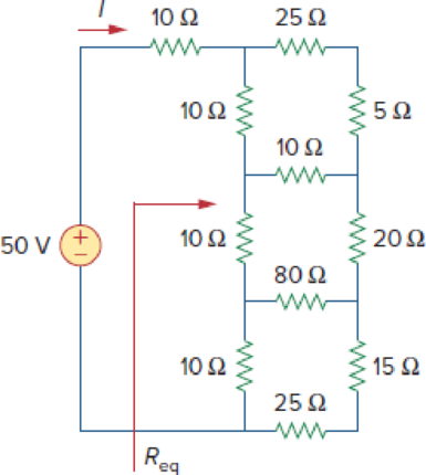
Find Req and I in the circuit of Fig. 2.121.
Figure 2.121
Calculate the values of equivalent resistance
Answer to Problem 57P
The values of equivalent resistance
Explanation of Solution
Formula used:
Consider the following delta to wye conversion, when all branches in a delta consist same value.
Consider the expression for
Here,
Consider the expression for
Calculation:
Refer to Figure 2.121 in the textbook For Prob.2.57.
Step 1:
In Figure 2.121, as
Step 2:
In Figure 2.121, as
Step 3:
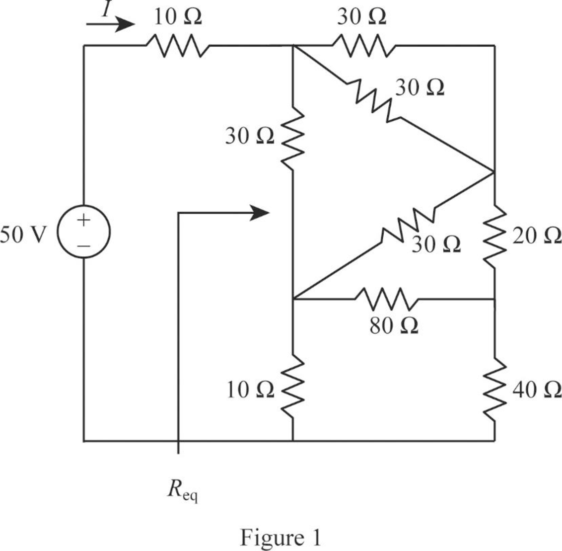
In Figure 2.121, convert the wye- sub network into delta connection.
Substitute
Since all branches values are same in a wye connection that is
Modify Figure 2.121 as shown in Figure 1.
Step 4:
In Figure 1, as
Modify Figure 1 as shown in Figure 2.
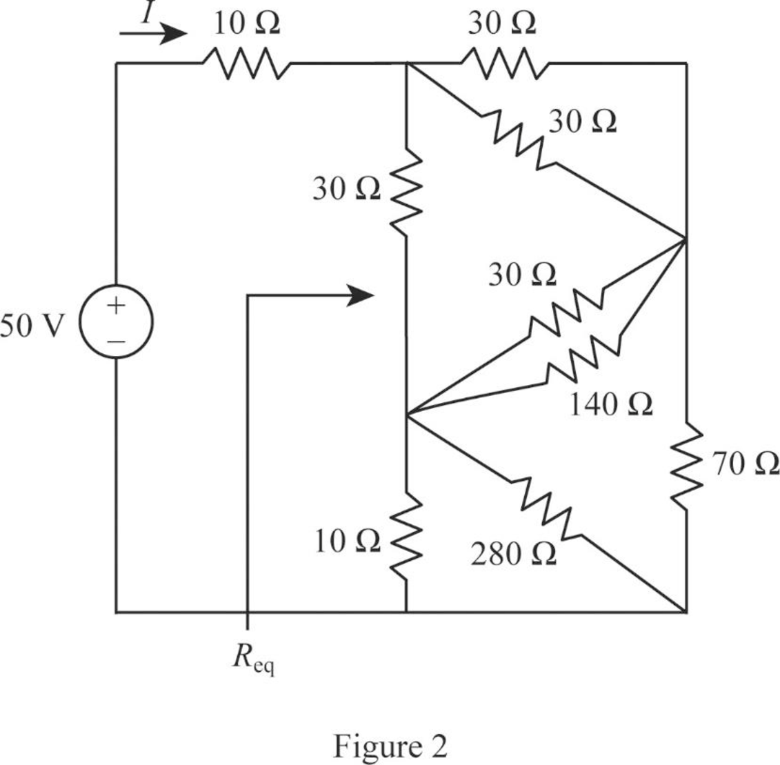
Step 5:
In Figure 2, as two
Step 6:
In Figure 2, as
Step 7:
In Figure 2, as
Modify Figure 2 as shown in Figure 3.
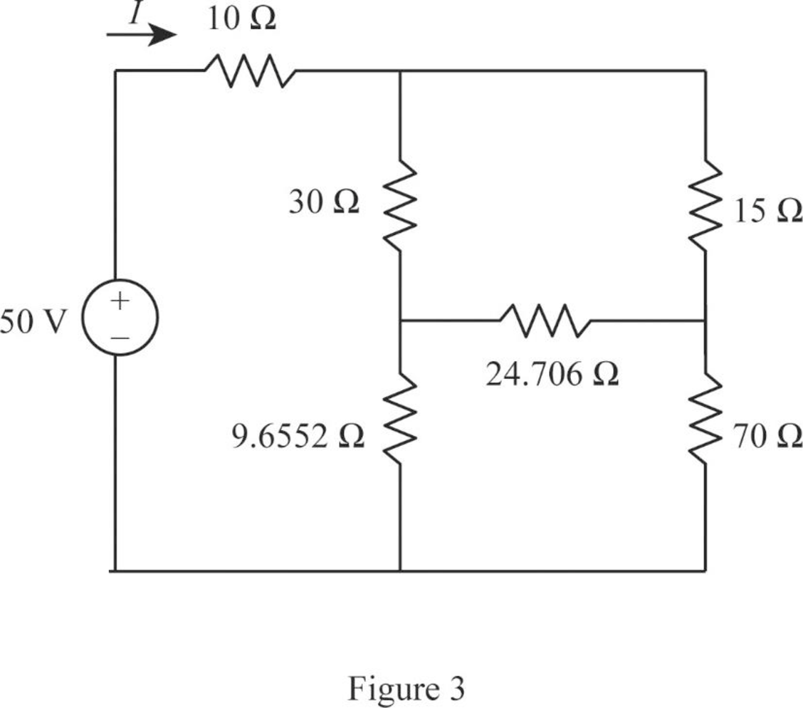
Step 8:
In Figure 3, as
Modify Figure 3 as shown in Figure 4.
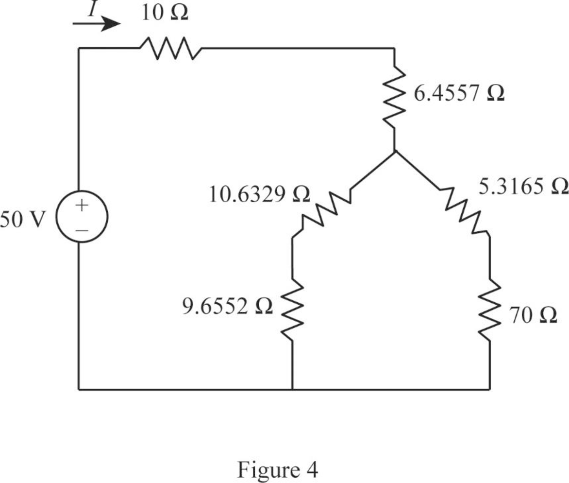
Step 9:
In Figure 4, as
Step 10:
In Figure 4, as
Step 11:
In Figure 4, as
Modify Figure 4 as shown in Figure 5.
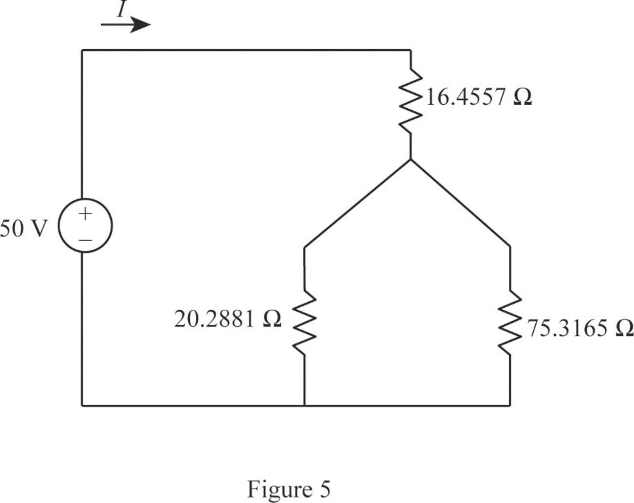
Step 12:
In Figure 5, as
Modify Figure 5 as shown in Figure 6.
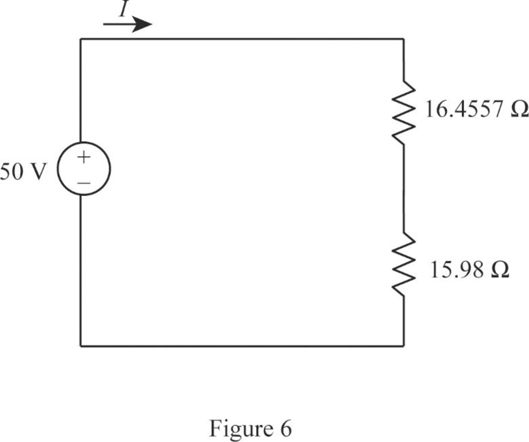
Step 13:
In Figure 6, as
Consider the general expression to find current
Conclusion:
Thus, the values of equivalent resistance
Want to see more full solutions like this?
Chapter 2 Solutions
EE 98: Fundamentals of Electrical Circuits - With Connect Access
Additional Engineering Textbook Solutions
Electric Circuits (10th Edition)
Electrical Engineering: Principles & Applications (7th Edition)
Principles Of Electric Circuits
Microelectronics: Circuit Analysis and Design
Basic Engineering Circuit Analysis
ANALYSIS+DESIGN OF LINEAR CIRCUITS(LL)


- Determine i, and i, in the circuit of Fig. 2.74. -8 A 4 A -10Aarrow_forward13. For the circuit shown in Fig. 2.181, determine current through RL when it takes values of 5 and 10 Ω. [0.588 A, 0.408 A]arrow_forwarda) Formulate node voltage equations for the circuits in figure 2. b) Solve VA, VB, Vc, Vx, Ix. + Vx- 1 mA VC VA VB 4kN 4 kN ix. 5 V 4 ΚΩΣ 2kΩarrow_forward
- Given the circuit in Fig. 2.78, use KVL to find the branch voltages V1 to V4. 3 V V1 V2 2 V +1 V3 4 V V4 5 Varrow_forward2.9 Find 11, 12, and i3 in the circuit in Fig. 2.73. 10 A IA 2 A Figure 2.73 For Prob. 2.9. 3 Aarrow_forwardfor the circuit in Fig. 2.77, use ĶCL to find the branch currents I to I4. 2 A 12 7 A ЗА 13 4 A 12= A 11 = A 14= A 13= A 1.arrow_forward
- Fill in the blanks / identification: ror the circuit in Fig. 2.77, use ĶCL to find the branch currents I, to l4. 2 A 7 A 4 A 12 = A 11 = A 14= A 13= A 3.arrow_forwardFind i, i2, and iz in Fig. 2.73. - 5A 15A i2 IOA A B -6 A 2 A - 1Aarrow_forwardQ₂ Q₂ Find (UCH) in the circuit of Figure below 1H Tort (1)V + ✓ CH 42 2.2 Farrow_forward
- Reduce each of the circuits in Fig. 2.106 to a single resistor at terminals a-b. 15Ω a o o b 20 Ω ww 500arrow_forward2.13 For the circuit in Fig. 2.77, use KCL to find the branch currents 1₁ to 14. 10/2 J 2 A 7 A 3 A 14 13 2 4 Aarrow_forwardExample: Find current i, and voltage in the circuit shown below using KCL 0.5 i ^ a + / CC 452arrow_forward
 Introductory Circuit Analysis (13th Edition)Electrical EngineeringISBN:9780133923605Author:Robert L. BoylestadPublisher:PEARSON
 Delmar's Standard Textbook Of ElectricityElectrical EngineeringISBN:9781337900348Author:Stephen L. HermanPublisher:Cengage Learning
 Programmable Logic ControllersElectrical EngineeringISBN:9780073373843Author:Frank D. PetruzellaPublisher:McGraw-Hill Education
 Fundamentals of Electric CircuitsElectrical EngineeringISBN:9780078028229Author:Charles K Alexander, Matthew SadikuPublisher:McGraw-Hill Education
 Electric Circuits. (11th Edition)Electrical EngineeringISBN:9780134746968Author:James W. Nilsson, Susan RiedelPublisher:PEARSON
 Engineering ElectromagneticsElectrical EngineeringISBN:9780078028151Author:Hayt, William H. (william Hart), Jr, BUCK, John A.Publisher:Mcgraw-hill Education,