
Concept explainers
Videos
Determine V in the circuit of Fig. 2.120.
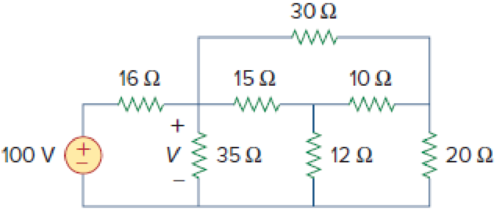
Figure 2.120
Calculate the value of voltage
Answer to Problem 56P
The value of voltage
Explanation of Solution
Formula used:
Consider the wye to delta conversions.
Here,
Consider the expression for
Here,
Consider the expression for
Calculation:
Refer to Figure 2.120 in the textbook For Prob.2.56.
Step 1:
From Figure 2.120, consider
Substitute
Substitute
Substitute
Modify Figure 2.120 as shown in Figure 1.
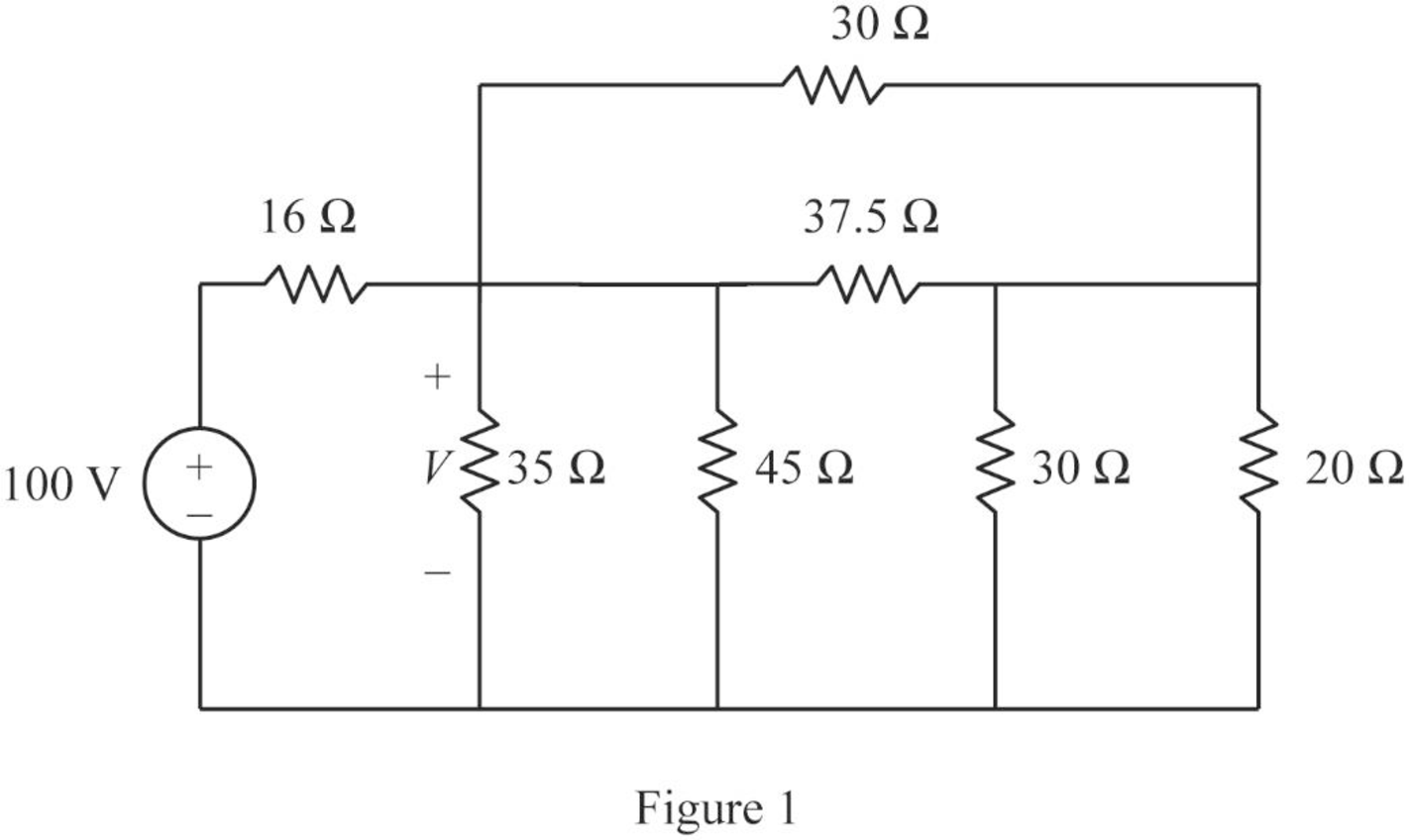
Step 2:
In Figure 1, as
Step 3:
In Figure 1, as
Step 4:
In Figure 1, as
Modify Figure 1 as shown in Figure 2.
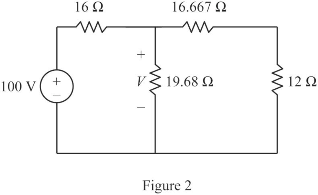
Step 5:
In Figure 2, as
Modify Figure 2 as shown in Figure 3.
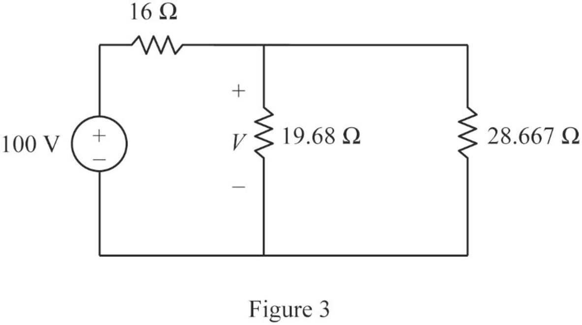
Step 6:
In Figure 3, as
Modify Figure 3 as shown in Figure 4.
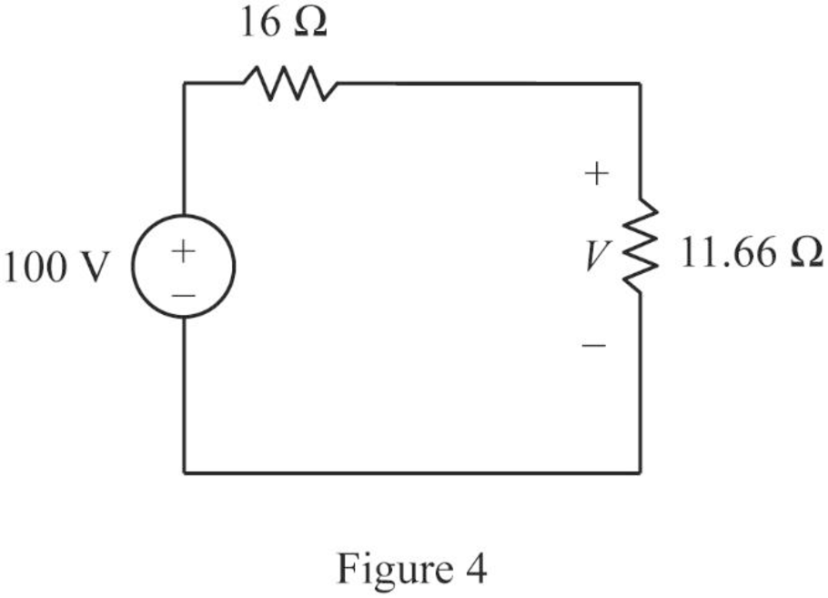
Step 7:
Apply voltage division rule to Figure 4.
Conclusion:
Thus, the value of voltage
Want to see more full solutions like this?
Chapter 2 Solutions
EBK FUNDAMENTALS OF ELECTRIC CIRCUITS


- 7. With the help of nodal analysis, find V1 and V2 and various branch currents in the network of Fig. 2.85. [5V,2.5V;Iac =2.5A;Iab =0.5A;Ibc =2.5A]arrow_forwardGiven the circuit in Fig. 2.101 and that the resis- tance, Reg, looking into the circuit from the left is equal to 200 2, determine the value of R1. eq» R1arrow_forward2.10 Determine ij and iz in the circuit of Fig. 2.74. -8 A 4 A -6 Aarrow_forward
- 2.9 Find 11, 12, and i3 in the circuit in Fig. 2.73. 10 A IA 2 A Figure 2.73 For Prob. 2.9. 3 Aarrow_forwardElectrical Circuit Analysis Lab. 2. Determine the equivalent resistance between the terminals a and b 452 my 0.666 0.6 0.33352arrow_forwardDetermine i, and iz in the circuit of Fig. 2.74. 4 A -2 A i2 ЗА i1 = || A 12 = A %3Darrow_forward
- Given the circuit in Fig. 2.101 and that the resis- tance, Reg, looking into the circuit from the left is equal to 200 2, determine the value of R1. eq+ R, R,arrow_forward11. State and explain Superposition theorem. For the circuit of Fig. 2.126. (a) determine currents I1, I2 and I3 when switch S is in position b. (b) using the results of part (a) and the principle of superposition, determine the same currents with switch S in position a.[(a) 15 A, 10 A, 25 A (b) 11 A , 16 A, 27 A]arrow_forward2.17 Obtain v₁ through v3 in the circuit of Fig. 2.81. 24 V Figure 2.81 For Prob. 2.17. V1 www + 12 V + www 1 03 +1 10 Varrow_forward
- Item 1 of 3 In the circuit in Fig. 2.76, obtain vị, v2, and v3. +20 V - 90 V- - 60 V + メ + v2 - + + 40 V + V3arrow_forwardBy applying nodal analysis to the circuit of Fig. 2.90, find Iab, Ibd and Ibc. All resistance values are in ohms. [Iab =22/21A,Ibd =10/7A, Ibc =−8/21A] [Hint. : It would be helpful to convert resistance into conductances.]arrow_forwardElectrical Circuit Analysis Lab. 2. Determine the equivalent resistance between the terminals a and b US 0.3332arrow_forward
 Introductory Circuit Analysis (13th Edition)Electrical EngineeringISBN:9780133923605Author:Robert L. BoylestadPublisher:PEARSON
 Delmar's Standard Textbook Of ElectricityElectrical EngineeringISBN:9781337900348Author:Stephen L. HermanPublisher:Cengage Learning
 Programmable Logic ControllersElectrical EngineeringISBN:9780073373843Author:Frank D. PetruzellaPublisher:McGraw-Hill Education
 Fundamentals of Electric CircuitsElectrical EngineeringISBN:9780078028229Author:Charles K Alexander, Matthew SadikuPublisher:McGraw-Hill Education
 Electric Circuits. (11th Edition)Electrical EngineeringISBN:9780134746968Author:James W. Nilsson, Susan RiedelPublisher:PEARSON
 Engineering ElectromagneticsElectrical EngineeringISBN:9780078028151Author:Hayt, William H. (william Hart), Jr, BUCK, John A.Publisher:Mcgraw-hill Education,