
Power System Analysis & Design
6th Edition
ISBN: 9781305636187
Author: Glover, J. Duncan, Overbye, Thomas J. (thomas Jeffrey), Sarma, Mulukutla S.
Publisher: Cengage Learning,
expand_more
expand_more
format_list_bulleted
Concept explainers
Videos
Textbook Question
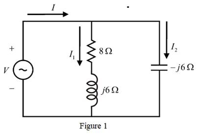
Chapter 2, Problem 2.4P
For the single-phase circuit shown in Figure 122,
Expert Solution & Answer

Trending nowThis is a popular solution!

Students have asked these similar questions
Finding equivalent impedance using phasor formAnd question 2 finding i
• What is the phasor form of
v(t)=172 sin(770f-34°) mV?
770 <172 mV
172 Z-34⁰ mV
770 <-34⁰ mV
172 2770° mV
1. For the circuit shown below, use the current divider rule to find the phasors 13
and Vo in polar form: answer: 13 = 7.694 65.3° A, V₁ =¹46.161 Z-24.7° V
1₁ = 940° A ↑
R₁
15 02
L₁
j8n
A₂
www.
4Ω
13↓
с
-j6n
Hii
+
V₂
R3
ΖΩ
L₂
j5Ω
Chapter 2 Solutions
Power System Analysis & Design
Ch. 2 - The rms value of v(t)=Vmaxcos(t+) is given by a....Ch. 2 - If the rms phasor of a voltage is given by V=12060...Ch. 2 - If a phasor representation of a current is given...Ch. 2 - Prob. 2.4MCQCh. 2 - Prob. 2.5MCQCh. 2 - Prob. 2.6MCQCh. 2 - Prob. 2.7MCQCh. 2 - Prob. 2.8MCQCh. 2 - Prob. 2.9MCQCh. 2 - The average value of a double-frequency sinusoid,...
Ch. 2 - The power factor for an inductive circuit (R-L...Ch. 2 - The power factor for a capacitive circuit (R-C...Ch. 2 - Prob. 2.13MCQCh. 2 - The instantaneous power absorbed by the load in a...Ch. 2 - Prob. 2.15MCQCh. 2 - With generator conyention, where the current...Ch. 2 - Consider the load convention that is used for the...Ch. 2 - Prob. 2.18MCQCh. 2 - The admittance of the impedance j12 is given by...Ch. 2 - Consider Figure 2.9 of the text, Let the nodal...Ch. 2 - The three-phase source line-to-neutral voltages...Ch. 2 - In a balanced three-phase Y-connected system with...Ch. 2 - In a balanced system, the phasor sum of the...Ch. 2 - Consider a three-phase Y-connected source feeding...Ch. 2 - For a balanced- load supplied by a balanced...Ch. 2 - A balanced -load can be converted to an...Ch. 2 - When working with balanced three-phase circuits,...Ch. 2 - The total instantaneous power delivered by a...Ch. 2 - The total instantaneous power absorbed by a...Ch. 2 - Under balanced operating conditions, consider the...Ch. 2 - One advantage of balanced three-phase systems over...Ch. 2 - While the instantaneous electric power delivered...Ch. 2 - Given the complex numbers A1=630 and A2=4+j5, (a)...Ch. 2 - Convert the following instantaneous currents to...Ch. 2 - The instantaneous voltage across a circuit element...Ch. 2 - For the single-phase circuit shown in Figure...Ch. 2 - A 60Hz, single-phase source with V=27730 volts is...Ch. 2 - (a) Transform v(t)=75cos(377t15) to phasor form....Ch. 2 - Let a 100V sinusoidal source be connected to a...Ch. 2 - Consider the circuit shown in Figure 2.23 in time...Ch. 2 - For the circuit shown in Figure 2.24, compute the...Ch. 2 - For the circuit element of Problem 2.3, calculate...Ch. 2 - Prob. 2.11PCh. 2 - The voltage v(t)=359.3cos(t)volts is applied to a...Ch. 2 - Prob. 2.13PCh. 2 - A single-phase source is applied to a...Ch. 2 - Let a voltage source v(t)=4cos(t+60) be connected...Ch. 2 - A single-phase, 120V(rms),60Hz source supplies...Ch. 2 - Consider a load impedance of Z=jwL connected to a...Ch. 2 - Let a series RLC network be connected to a source...Ch. 2 - Consider a single-phase load with an applied...Ch. 2 - A circuit consists of two impedances, Z1=2030 and...Ch. 2 - An industrial plant consisting primarily of...Ch. 2 - The real power delivered by a source to two...Ch. 2 - A single-phase source has a terminal voltage...Ch. 2 - A source supplies power to the following three...Ch. 2 - Consider the series RLC circuit of Problem 2.7 and...Ch. 2 - A small manufacturing plant is located 2 km down a...Ch. 2 - An industrial load consisting of a bank of...Ch. 2 - Three loads are connected in parallel across a...Ch. 2 - Prob. 2.29PCh. 2 - Figure 2.26 shows three loads connected in...Ch. 2 - Consider two interconnected voltage sources...Ch. 2 - Prob. 2.35PCh. 2 - Prob. 2.36PCh. 2 - Prob. 2.37PCh. 2 - Prob. 2.38PCh. 2 - Prob. 2.39PCh. 2 - A balanced three-phase 240-V source supplies a...Ch. 2 - Prob. 2.41PCh. 2 - A balanced -connected impedance load with (12+j9)...Ch. 2 - A three-phase line, which has an impedance of...Ch. 2 - Two balanced three-phase loads that are connected...Ch. 2 - Two balanced Y-connected loads, one drawing 10 kW...Ch. 2 - Three identical impedances Z=3030 are connected in...Ch. 2 - Two three-phase generators supply a three-phase...Ch. 2 - Prob. 2.48PCh. 2 - Figure 2.33 gives the general -Y transformation....Ch. 2 - Consider the balanced three-phase system shown in...Ch. 2 - A three-phase line with an impedance of...Ch. 2 - A balanced three-phase load is connected to a...Ch. 2 - What is a microgrid?Ch. 2 - What are the benefits of microgrids?Ch. 2 - Prob. CCSQCh. 2 - Prob. DCSQ
Knowledge Booster


Learn more about
Need a deep-dive on the concept behind this application? Look no further. Learn more about this topic, electrical-engineering and related others by exploring similar questions and additional content below.Similar questions
- 3. Determine the phasor current Io and phasor voltage Vo in the following circuit. 14 2 I. 1:5 3:4 2420°V Vo 60 Q 160 N u uarrow_forwardFor the circuit shown in figure below, Find the current I3 by using the loop (Mesh) method. 40 + j15 2 25 - j50 2 48 /75° V 13 - j50 2 j40 N 32 + j16 2arrow_forwardA two element series circuit R= 5 ohm and XC=5 ohm has an effective applied voltage of 120V . Determine the power trainglearrow_forward
- The terminal voltage for cases where the cosQ value is reverse, forward and 1, respectively, ignoring the resistance value of the generator draw phasor diagramsarrow_forward1. Draw the circuits in Figure 1 the phasor domain.2. Calculate the circuit total impedance.3. Calculate i vr and vlarrow_forward7. In Figure E, use the voltage divider rule to compute the phasor voltage Vo. Frequency is 60 Hz. 2520⁰ V www 10 Ω 378.9403μF 15 Ω Figure E Vo 321.1107mHarrow_forward
- Question 3 (1 point) In a series R-L-C AC circuit, the total impedance Ztot will always be larger (or equal) in magnitude than: R every single reactance in the circuit XL Xcarrow_forwardCalculate the voltages at nodes 1 and 2 in the circuit given below using nodal analysis, where Is = 60 / 30° A. Please report your answer so the magnitude is positive and all angles are in the range of negative 180 degrees to positive 180 degrees. j4Ω m Is -j2Q2 1 1092 The voltage at node 1 is V₁ = The voltage at node 2 is V₂ = j2 Q2 2 -j5Q 136.378 ° V. 125.042 ° V.arrow_forwardDetermine the phase currents for the given Δ-Δ circuit. Please report your answer so the magnitude is positive and all angles are in the range of negative 180 degrees to positive 180 degrees.arrow_forward
- V₁ 20Vp-p N D'₁ D₂ RL Yo S V₂ = 20 Vp-p Vi is out of phase with √₂ by 180°arrow_forward15. Find the Line and Phase Currents of the Circuit R1 L4 0.5mH R5 50 R6 V4 L1 L2 R2 L5 R4 30µH L3 30μH 10 0.5mH 120 V 60 Hz 30µH R3 L6 0.5mHarrow_forwardA solenoid with an inductance of 0.25 H and a resistance of 100 Q is connected to a 120-V 60-Hz source. The current is: Please check the closest answer that applies. X L 120 V 60 Hz O0.226 2-16.3° A O0.224 2-31.2° A LOarrow_forward
arrow_back_ios
SEE MORE QUESTIONS
arrow_forward_ios
Recommended textbooks for you
 Power System Analysis and Design (MindTap Course ...Electrical EngineeringISBN:9781305632134Author:J. Duncan Glover, Thomas Overbye, Mulukutla S. SarmaPublisher:Cengage Learning
Power System Analysis and Design (MindTap Course ...
Electrical Engineering
ISBN:9781305632134
Author:J. Duncan Glover, Thomas Overbye, Mulukutla S. Sarma
Publisher:Cengage Learning
Current Divider Rule; Author: Neso Academy;https://www.youtube.com/watch?v=hRU1mKWUehY;License: Standard YouTube License, CC-BY