
POWER SYS. ANALYSIS+DESIGN
6th Edition
ISBN: 9780357700907
Author: Glover
Publisher: INTER CENG
expand_more
expand_more
format_list_bulleted
Concept explainers
Videos
Textbook Question
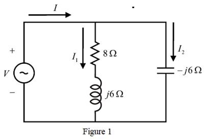
Chapter 2, Problem 2.4P
For the single-phase circuit shown in Figure 122,
Expert Solution & Answer

Trending nowThis is a popular solution!

Students have asked these similar questions
Finding equivalent impedance using phasor formAnd question 2 finding i
• What is the phasor form of
v(t)=172 sin(770f-34°) mV?
770 <172 mV
172 Z-34⁰ mV
770 <-34⁰ mV
172 2770° mV
1. For the circuit shown below, use the current divider rule to find the phasors 13
and Vo in polar form: answer: 13 = 7.694 65.3° A, V₁ =¹46.161 Z-24.7° V
1₁ = 940° A ↑
R₁
15 02
L₁
j8n
A₂
www.
4Ω
13↓
с
-j6n
Hii
+
V₂
R3
ΖΩ
L₂
j5Ω
Chapter 2 Solutions
POWER SYS. ANALYSIS+DESIGN
Ch. 2 - The rms value of v(t)=Vmaxcos(t+) is given by a....Ch. 2 - If the rms phasor of a voltage is given by V=12060...Ch. 2 - If a phasor representation of a current is given...Ch. 2 - Prob. 2.4MCQCh. 2 - Prob. 2.5MCQCh. 2 - Prob. 2.6MCQCh. 2 - Prob. 2.7MCQCh. 2 - Prob. 2.8MCQCh. 2 - Prob. 2.9MCQCh. 2 - The average value of a double-frequency sinusoid,...
Ch. 2 - The power factor for an inductive circuit (R-L...Ch. 2 - The power factor for a capacitive circuit (R-C...Ch. 2 - Prob. 2.13MCQCh. 2 - The instantaneous power absorbed by the load in a...Ch. 2 - Prob. 2.15MCQCh. 2 - With generator conyention, where the current...Ch. 2 - Consider the load convention that is used for the...Ch. 2 - Prob. 2.18MCQCh. 2 - The admittance of the impedance j12 is given by...Ch. 2 - Consider Figure 2.9 of the text, Let the nodal...Ch. 2 - The three-phase source line-to-neutral voltages...Ch. 2 - In a balanced three-phase Y-connected system with...Ch. 2 - In a balanced system, the phasor sum of the...Ch. 2 - Consider a three-phase Y-connected source feeding...Ch. 2 - For a balanced- load supplied by a balanced...Ch. 2 - A balanced -load can be converted to an...Ch. 2 - When working with balanced three-phase circuits,...Ch. 2 - The total instantaneous power delivered by a...Ch. 2 - The total instantaneous power absorbed by a...Ch. 2 - Under balanced operating conditions, consider the...Ch. 2 - One advantage of balanced three-phase systems over...Ch. 2 - While the instantaneous electric power delivered...Ch. 2 - Given the complex numbers A1=630 and A2=4+j5, (a)...Ch. 2 - Convert the following instantaneous currents to...Ch. 2 - The instantaneous voltage across a circuit element...Ch. 2 - For the single-phase circuit shown in Figure...Ch. 2 - A 60Hz, single-phase source with V=27730 volts is...Ch. 2 - (a) Transform v(t)=75cos(377t15) to phasor form....Ch. 2 - Let a 100V sinusoidal source be connected to a...Ch. 2 - Consider the circuit shown in Figure 2.23 in time...Ch. 2 - For the circuit shown in Figure 2.24, compute the...Ch. 2 - For the circuit element of Problem 2.3, calculate...Ch. 2 - Prob. 2.11PCh. 2 - The voltage v(t)=359.3cos(t)volts is applied to a...Ch. 2 - Prob. 2.13PCh. 2 - A single-phase source is applied to a...Ch. 2 - Let a voltage source v(t)=4cos(t+60) be connected...Ch. 2 - A single-phase, 120V(rms),60Hz source supplies...Ch. 2 - Consider a load impedance of Z=jwL connected to a...Ch. 2 - Let a series RLC network be connected to a source...Ch. 2 - Consider a single-phase load with an applied...Ch. 2 - A circuit consists of two impedances, Z1=2030 and...Ch. 2 - An industrial plant consisting primarily of...Ch. 2 - The real power delivered by a source to two...Ch. 2 - A single-phase source has a terminal voltage...Ch. 2 - A source supplies power to the following three...Ch. 2 - Consider the series RLC circuit of Problem 2.7 and...Ch. 2 - A small manufacturing plant is located 2 km down a...Ch. 2 - An industrial load consisting of a bank of...Ch. 2 - Three loads are connected in parallel across a...Ch. 2 - Prob. 2.29PCh. 2 - Figure 2.26 shows three loads connected in...Ch. 2 - Consider two interconnected voltage sources...Ch. 2 - Prob. 2.35PCh. 2 - Prob. 2.36PCh. 2 - Prob. 2.37PCh. 2 - Prob. 2.38PCh. 2 - Prob. 2.39PCh. 2 - A balanced three-phase 240-V source supplies a...Ch. 2 - Prob. 2.41PCh. 2 - A balanced -connected impedance load with (12+j9)...Ch. 2 - A three-phase line, which has an impedance of...Ch. 2 - Two balanced three-phase loads that are connected...Ch. 2 - Two balanced Y-connected loads, one drawing 10 kW...Ch. 2 - Three identical impedances Z=3030 are connected in...Ch. 2 - Two three-phase generators supply a three-phase...Ch. 2 - Prob. 2.48PCh. 2 - Figure 2.33 gives the general -Y transformation....Ch. 2 - Consider the balanced three-phase system shown in...Ch. 2 - A three-phase line with an impedance of...Ch. 2 - A balanced three-phase load is connected to a...Ch. 2 - What is a microgrid?Ch. 2 - What are the benefits of microgrids?Ch. 2 - Prob. CCSQCh. 2 - Prob. DCSQ
Knowledge Booster


Learn more about
Need a deep-dive on the concept behind this application? Look no further. Learn more about this topic, electrical-engineering and related others by exploring similar questions and additional content below.Similar questions
- 3. Determine the phasor current Io and phasor voltage Vo in the following circuit. 14 2 I. 1:5 3:4 2420°V Vo 60 Q 160 N u uarrow_forwardFor the circuit shown in figure below, Find the current I3 by using the loop (Mesh) method. 40 + j15 2 25 - j50 2 48 /75° V 13 - j50 2 j40 N 32 + j16 2arrow_forwardA two element series circuit R= 5 ohm and XC=5 ohm has an effective applied voltage of 120V . Determine the power trainglearrow_forward
- 1. Draw the circuits in Figure 1 the phasor domain.2. Calculate the circuit total impedance.3. Calculate i vr and vlarrow_forwardThe terminal voltage for cases where the cosQ value is reverse, forward and 1, respectively, ignoring the resistance value of the generator draw phasor diagramsarrow_forward7. In Figure E, use the voltage divider rule to compute the phasor voltage Vo. Frequency is 60 Hz. 2520⁰ V www 10 Ω 378.9403μF 15 Ω Figure E Vo 321.1107mHarrow_forward
- Question 3 (1 point) In a series R-L-C AC circuit, the total impedance Ztot will always be larger (or equal) in magnitude than: R every single reactance in the circuit XL Xcarrow_forwardDetermine the phase currents for the given Δ-Δ circuit. Please report your answer so the magnitude is positive and all angles are in the range of negative 180 degrees to positive 180 degrees.arrow_forwardCalculate the voltages at nodes 1 and 2 in the circuit given below using nodal analysis, where Is = 60 / 30° A. Please report your answer so the magnitude is positive and all angles are in the range of negative 180 degrees to positive 180 degrees. j4Ω m Is -j2Q2 1 1092 The voltage at node 1 is V₁ = The voltage at node 2 is V₂ = j2 Q2 2 -j5Q 136.378 ° V. 125.042 ° V.arrow_forward
- 15. Find the Line and Phase Currents of the Circuit R1 L4 0.5mH R5 50 R6 V4 L1 L2 R2 L5 R4 30µH L3 30μH 10 0.5mH 120 V 60 Hz 30µH R3 L6 0.5mHarrow_forwardV₁ 20Vp-p N D'₁ D₂ RL Yo S V₂ = 20 Vp-p Vi is out of phase with √₂ by 180°arrow_forward3. For the following circuit determine (include and show all the steps): (4 marks) a. Total impedance in polar form b. Total current in polar form C. Phase angle between source voltage and total current d. Phasor diagram of voltage and currents in the circuit XL 100 R Хс 220 150 Q Vs 1 <0° Vrms ACarrow_forward
arrow_back_ios
SEE MORE QUESTIONS
arrow_forward_ios
Recommended textbooks for you
 Power System Analysis and Design (MindTap Course ...Electrical EngineeringISBN:9781305632134Author:J. Duncan Glover, Thomas Overbye, Mulukutla S. SarmaPublisher:Cengage Learning
Power System Analysis and Design (MindTap Course ...
Electrical Engineering
ISBN:9781305632134
Author:J. Duncan Glover, Thomas Overbye, Mulukutla S. Sarma
Publisher:Cengage Learning
Current Divider Rule; Author: Neso Academy;https://www.youtube.com/watch?v=hRU1mKWUehY;License: Standard YouTube License, CC-BY