
Concept explainers
Videos
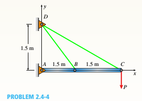
A horizontal rigid bar ABC is pinned at end A and supported by two cables at points B and C. A vertical load P = 10 kN acts at end C of the bar. The two cables are made of steel with a modulus elasticity E = 200 GPa and have the same cross-sectional area. Calculate the minimum cross-sectional area of each cable if the yield stress of the cable is 400 MPa and the factor of safely is 2.0. Consider load P only; ignore the weight of bar ABC and the cables.
The minimum cross-section area of each cable.
Answer to Problem 2.4.4P
The minimum cross-section area of each cable is
Explanation of Solution
The vertical load is
The below figure represents the free body diagram of the cable.
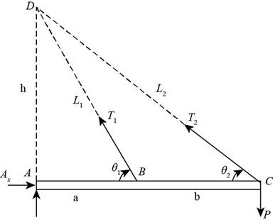
Figure-(1)
Here, the length of the portion AB is
Write the expression for the length of the cable 1.
Here, length of the cable 1 is
Write the expression for the length of the cable 2.
Here, length of the cable 2 is
Write the expression for the angle for cable 1 which makes from horizontal.
Write the expression for the angle for cable 1 which makes from horizontal.
Write the expression for the moment about the point A.
Here, the tension in cable 1 is
The below figure represents the displacement diagram.
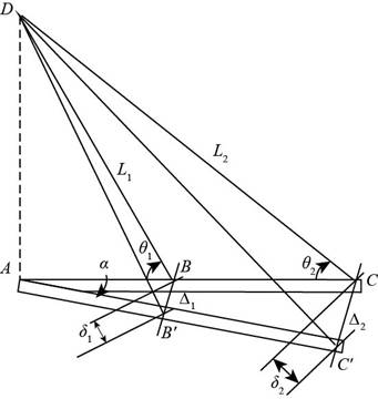
Figure-(2)
Here, displacement for cable 1 is
Write the expression for the displacement assuming this is a small displacement.
Write the expression for the displacement of portion AB.
Write the expression for the displacement of portion AC.
Write the expression for the deflection in cable 1.
Here, area of the cross-section is
Write the expression for the deflection in cable 2.
Here, the deflection in cable 2 is
Write the expression for the stress equation considering factor of safety for cable 1.
Here, the factor of safety is
Write the expression for the stress equation considering factor of safety for cable 2.
Calculation:
Substitute
Substitute
Substitute
Substitute
Substitute
Substitute
Substitute
Substitute
Substitute
Substitute
Substitute
Substitute
Substitute
Conclusion:
The minimum cross- section area is calculated by equating modulus of stress, elasticity, cable and factor of safety,height and length of cable.
Want to see more full solutions like this?
Chapter 2 Solutions
Bundle: Mechanics Of Materials, Loose-leaf Version, 9th + Mindtap Engineering, 1 Term (6 Months) Printed Access Card


- A long, rectangular copper bar under a tensile load P hangs from a pin that is supported by two steel posts (see figure). The copper bar has a length of 2.0 m, a cross-sectional area of4S00 mm", and a modulus of elasticity Ec= 120 GPa. Each steel post has a height of 0.5 m, a cross-sectional area of 4500 mm2, and a modulus of elasticity E = 200 GRa. (a) Determine the downward displacementarrow_forwardA vertical bar is loaded with axial loads at points B, C, and D. as shown in the figure. The bar is made of steel with a modulus of elasticity E = 29,000 ksi., The bar has a cross-sectional area of 8.24 in2. Calculate the displacements at points B, C, and D. Ignore the weight of the bararrow_forwardWires B and C are attached to a support at the left-hand end and to a pin-supported rigid bar at the right-hand end (see figure). Each wire has cross-sectional area A =0.03 in2 and modulus of elasticity E = 30 X 106 psi. When the bar is in a vertical position, the length of each wire is L = 80 in. However, before being attached to the bar, the length of wire B was 79.98 in. and wire C was 79.95 in. Find the tensile forces TBand Tc in the wires under the action of a force P = 700 lb acting at the upper end of the bar.arrow_forward
- An aluminum bar subjected to tensile Forces P has a length L = 150 in. and cross-sectional area A = 2.0 in2 The stress-strain behavior of the aluminum may be represented approximately by the bilinear stress-strain diagram shown in the figure. Calculate the elongation S of the bar for each of the following axial loads: p = 8 kips, 16 kips. 24 kips, 32 kips, and 40 kips. From these results, plot a diagram of load P versus elongation S (load-displacement diagram).arrow_forwardA three-story steel column in a building supports roof and floor loads as shown in the figure. The story height H is 10.5 ft. the cross-sectional area A of the column is 15.5 in2, and the modulus of elasticity E of the steel is 30 × 106 psi. Calculate the strain energy U of the column assuming P1= 40 kips and P2= P3= 60 kips.arrow_forwardA copper bar AB with a length 25 in. and diameter 2 in. is placed in position at room temperature with a gap of 0.008 in. between end A and a rigid restraint (see figure). The bar is supported at end B by an elastic spring with a spring constant k= 1.2 × 10⁶ lb/in. (a) Calculate the axial compressive stress crcin the bar if the temperature of the bar only rises 50 F. (For copper, use a = 9.6 × 10⁻⁶/ and E = 16 × 106 psi.) (b) What is the force in the spring? (Neglect gravity effects.) (c) Repeat part (a) if k ? 8.arrow_forward
- Two pipe columns (AB, FC) are pin-connected to a rigid beam (BCD), as shown in the figure. Each pipe column has a modulus of E, but heights (L1or L2) and outer diameters (d1or different for each column. Assume the inner diameter of each column is 3/4 of outer diameter. Uniformly distributed downward load q = 2PIL is applied over a distance of 3L/4 along BC, and concentrated load PIA is applied downward at D. (a) Derive a formula for the displacementarrow_forwardA round bar of 10 mm diameter is made of aluminum alloy 7075-T6 (see figure). When the bar is stretched by axial forces P, its diameter decreases by 0.0 16 mm. Find the magnitude of the load P. Obtain the material properties from Appendix 1.arrow_forwardA rigid bar AB having a mass M = 1.0 kg and length L = 0.5 m is hinged at end A and supported at end B by a nylon cord BC (see figure). The record has cross-sectional area A = 30 mm2. length b = 0.25 m. and modulus of elasticity E = 2.1 GPa. If the bar is raised to its maximum height and then released, what is the maximum stress in the cord?arrow_forward
- A long, slender bar in the shape of a right circular cone with length L and base diameter d hangs vertically under the action of its own weight (see figure). The weight of the cone is W and the modulus of elasticity of the material is E. Derive a formula for the increase S in the length of the bar due to its own weight. (Assume that the angle of taper of the cone is small.)arrow_forwardA rigid bar ACB is supported on a fulcrum at C and loaded by a Force P at end B (see figure). Three identical wires made of an elasloplastic material (yield stress oYand modulus of elasticity E) resist tbe load P. Each wire has cross-sectional area A and length L. (a) Determine the yield load PYand the corresponding yield displacement Syat point B. (b) Determine the plastic load PPand the corresponding displacementarrow_forwardA rigid bar AB is pinned al end A and is supported by a wine CD and loaded by a force P at end B (see figure). The wire is made of high-strength steel having a modulus of elasticity E = 210 GPa and yield stress ??Y= 820 MPa. The length of the wire is L = 1.0 m. and its diameter is d = 3 mm. The stress-strain diagram for the steel is defined by the riuniift-ed power taw. asarrow_forward
 Mechanics of Materials (MindTap Course List)Mechanical EngineeringISBN:9781337093347Author:Barry J. Goodno, James M. GerePublisher:Cengage Learning