
Industrial Motor Control
7th Edition
ISBN: 9781133691808
Author: Stephen Herman
Publisher: Cengage Learning
expand_more
expand_more
format_list_bulleted
Concept explainers
Question
thumb_up100%
Chapter 2, Problem 1RQ
To determine
The name of the symbol from the given options.
Expert Solution & Answer
Explanation of Solution
The symbol shown in Figure 1 is used in a schematic of control circuits to designate normally open contact.
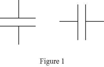
Two parallel horizontal lines or vertical lines are used to indicate a normally open contact. The normally open contact in a circuit schematic depicts that the circuit is open and no current flow is present.
Thus, the correct answer is “option d. Normally open contact”.
Want to see more full solutions like this?
Subscribe now to access step-by-step solutions to millions of textbook problems written by subject matter experts!
Students have asked these similar questions
Write short note on cathode protection
3. A contact device installed at the outlet for the connection of a single attachment plug. a. male plug b. switch c. female plug d. receptacle
Chapter 2 Solutions
Industrial Motor Control
Ch. 2 - Prob. 1RQCh. 2 - The symbol shown is: a. Normally closed float...Ch. 2 - The symbol shown is a(n)
iron core...Ch. 2 - The symbol shown is: a. Normally open pressure...Ch. 2 - The symbol shown is: a. Double acting push button...Ch. 2 - If you were installing the circuit in Figure 2–22,...Ch. 2 - Referring to the circuit in Figure 222, should the...Ch. 2 - Prob. 8RQCh. 2 - Prob. 9RQCh. 2 - When reading a schematic diagram, are the control...
Knowledge Booster


Learn more about
Need a deep-dive on the concept behind this application? Look no further. Learn more about this topic, mechanical-engineering and related others by exploring similar questions and additional content below.Similar questions
- What does the arrow pointing away from a diode symbol indicate?arrow_forwardThe symbol shown is: a. Iron core transformer b. Auto transformer c. Current transformer d. Air core transformerarrow_forwardThree common controls used in central electric heat applications are thermostats, contactors (or relays), and A. capacitors. B. sequencers. C. cool anticipators.arrow_forward
arrow_back_ios
arrow_forward_ios
Recommended textbooks for you
 Understanding Motor ControlsMechanical EngineeringISBN:9781337798686Author:Stephen L. HermanPublisher:Delmar Cengage Learning
 Refrigeration and Air Conditioning Technology (Mi...Mechanical EngineeringISBN:9781305578296Author:John Tomczyk, Eugene Silberstein, Bill Whitman, Bill JohnsonPublisher:Cengage Learning
 Electrical Transformers and Rotating MachinesMechanical EngineeringISBN:9781305494817Author:Stephen L. HermanPublisher:Cengage Learning
Understanding Motor Controls
Mechanical Engineering
ISBN:9781337798686
Author:Stephen L. Herman
Publisher:Delmar Cengage Learning
Refrigeration and Air Conditioning Technology (Mi...
Mechanical Engineering
ISBN:9781305578296
Author:John Tomczyk, Eugene Silberstein, Bill Whitman, Bill Johnson
Publisher:Cengage Learning
Electrical Transformers and Rotating Machines
Mechanical Engineering
ISBN:9781305494817
Author:Stephen L. Herman
Publisher:Cengage Learning