
Videos
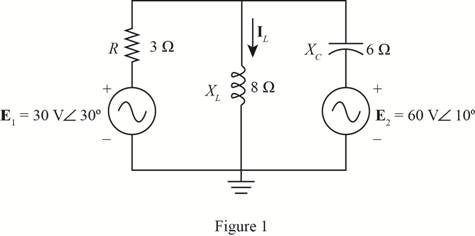
Using supeerposition, determine the current through the inductance XL for the network of Fig. 19.105.
The current flowing through the inductance
Answer to Problem 1P
The current through the inductor is
Explanation of Solution
Given:
The given circuit is shown in Figure 1.
Calculation:
To apply superposition theorem, first consider the effect of voltage source
The required diagram is shown in Figure 2.
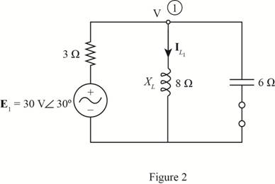
Let the voltage at node 1 is
The current through the inductor is given by
Substitute
Now consider the effect of source voltage
The required diagram is shown in Figure 3.
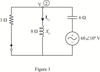
Apply the KCL at node 2.
The current through the inductor is given by,
Therefore, according to super position theorem the current through the inductor is given by
Substitute
Conclusion:
Therefore, the current through the inductor is
Want to see more full solutions like this?
Chapter 19 Solutions
Laboratory Manual for Introductory Circuit Analysis


- *14. For the circuit of Fig. 19.51: a. Find the total number of watts, volt-amperes reactive, and volt-amperes, and F. b. Find the current I.. c. Find the type of elements and their impedance in each box. (Assume that the elements within each box are in series.) Load 2 30 W 40 VAR (L) Load 1 Load 3 E = 100 V 20 (2) 200 W Fp = 1 FIG. 19.51 100 VAR (L) Fp = 0arrow_forward*14. For the circuit of Fig. 19.51: a. Find the total number of watts, volt-amperes reactive, and volt-amperes, and Fp. b. Find the current I.. c. Find the type of elements and their impedance in each box. (Assume that the elements within each box are in series.) Load 2 30 W 40 VAR (Z) Load 1 Load 3 E = 100 V 20° 200 W F₂ = 1 FIG. 19.51 100 VAR (L) F₂ = 0arrow_forwardPZ|| Determine the ABCD Parameters for the two port V23 -24 2₂ 24 V2 73 75arrow_forward
- QI find the Value of c so that the network impedance is Resistive at a hequ encyof 2KHZarrow_forwardE = 50 V 260° Load 1 Load 2 5. For the system of Fig. 19.44: a. Find PT. Qr, and St. b. Find the power factor F- c. Draw the power triangle. d. Find I,. Load 4 200 VAR (C) 100 W 100 VAR (Z) 200 W 100 VAR (L) 200 W Load 3 200 VAR (C) OWarrow_forward3. For the system given below a. Find the OLTFarrow_forward
- 10. A circuit consists of a pure resistance and a coil in series. The power dissipated in the resistance is 500 W and the drop across it is 100 V. The power dissipated in the coil is 100 W and the drop across it is 50 V. Find the reactance and resistance of the coil and the supply voltage. 19.1682 40 128.5V]arrow_forwardDetermine the following for the network shown below: a. b ZiAMP C. ZOAMP d. Given parameters: R1 = 20 ΜΩ R2 = 5 ΜΩ RD = 3.3 kΩ Rs = 2 kΩ Rsig = 1000 2 R = 1.5 ΚΩ VDD = 22 V AVAMP Rig 5+ IDss = 9 mA VP = -6 V yos = 25 μµS C₁ = 0.02 μF C₂ = 1 μF Cs = 2.2 µF J1 RS 0+ VDD w Aarrow_forwardSketch vo for each network and explain your solution.arrow_forward
- s/۸,۱ 2 30 1[ ۳۸ ١:٥٢ م 4.jpg → *14. For the circuit of Fig. 19.51: a. Find the total number of watts, volt-amperes reactive, and volt-amperes, and Fp- b. Find the current I.. c. Find the type of elements and their impedance in each box. (Assume that the elements within each box are in series.) Load 2 30 W 40 VAR (L) L Load 1 Load 3 ... E = 100 V 20° O 200 W Fp = 1 FIG. 19.51 100 VAR (Z) = 0arrow_forward(a) A voltmeter and an ammeter can be connected as shown in Fig. 19-83a to measure a resistance R. If V is the voltmeter reading, and / is the ammeter reading, the value of R will not quite be VI (as in Ohn's law) because some current goes through the voltmeter. Show that the actual value of Ris 1 I 1 - R V Ry Where Ry is the voltrneter resistance. Note that R z V/I if Ry > R. (b) A voltmeter and an ammeter can also be connected as shown in Fig. 19-83b to measure a resistance R. Show in this case that V R RA, I where Vand / are the voltmeter and ammeter readings and Ra is the resistance of the arnmeter. Note that R = V/I if RA « R. V A A R R (a) (b)arrow_forward9. Using superposition, determine the current IT (h = 100) for the network of Fig. 19.113. E 10 VZ0° + I= 2 mA 20⁰ hI R HI 20 ΚΩ XL IL 10 ΚΩarrow_forward
 Introductory Circuit Analysis (13th Edition)Electrical EngineeringISBN:9780133923605Author:Robert L. BoylestadPublisher:PEARSON
 Delmar's Standard Textbook Of ElectricityElectrical EngineeringISBN:9781337900348Author:Stephen L. HermanPublisher:Cengage Learning
 Programmable Logic ControllersElectrical EngineeringISBN:9780073373843Author:Frank D. PetruzellaPublisher:McGraw-Hill Education
 Fundamentals of Electric CircuitsElectrical EngineeringISBN:9780078028229Author:Charles K Alexander, Matthew SadikuPublisher:McGraw-Hill Education
 Electric Circuits. (11th Edition)Electrical EngineeringISBN:9780134746968Author:James W. Nilsson, Susan RiedelPublisher:PEARSON
 Engineering ElectromagneticsElectrical EngineeringISBN:9780078028151Author:Hayt, William H. (william Hart), Jr, BUCK, John A.Publisher:Mcgraw-hill Education,