
Concept explainers
Videos
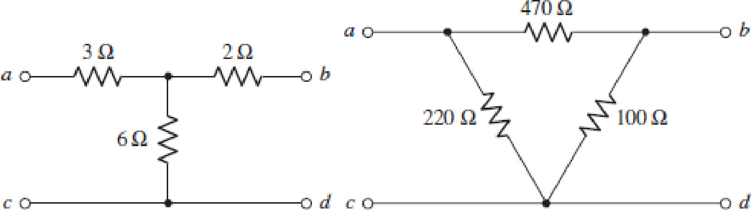
The two-port networks of Fig. 16.50 are connected in series. (a) Determine the impedance parameters for the series connection by first finding the z parameters of the individual networks. (b) If the two networks are instead connected in parallel, determine the admittance parameters of the combination by first finding the y parameters of the individual networks. (c) Verify your answer to part (b) by using Table 16.1 in conjunction with your answer to part (a).
(a)
The value of impedance parameters for the given condition.
Answer to Problem 35E
The value of total impedance when the two port networks are connected in series is
Explanation of Solution
Given data:
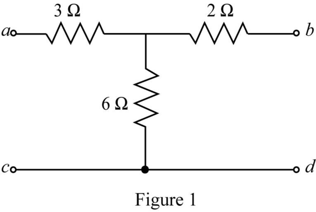
The given diagram is shown in Figure 1.
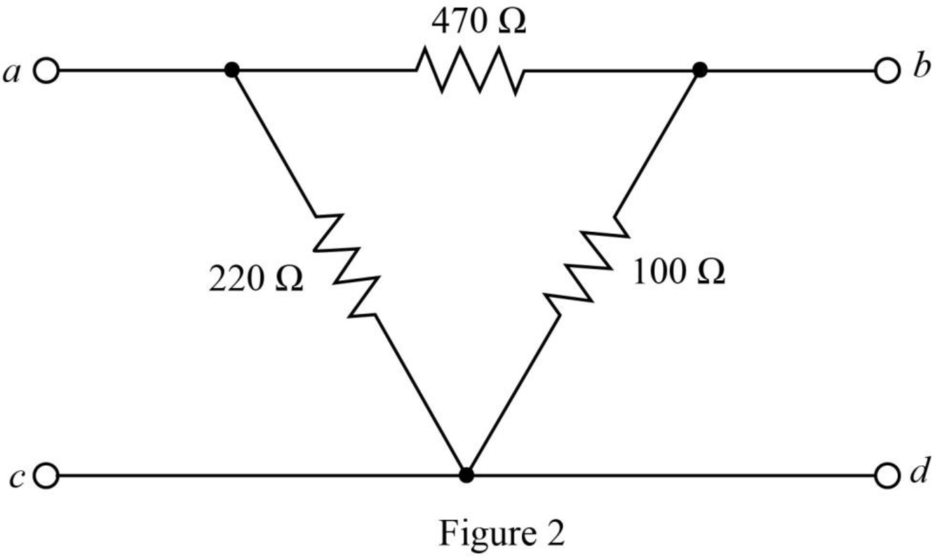
The given diagram is shown in Figure 2.
Calculation:
Determine the impedance parameter
The required diagram is shown in Figure 3.
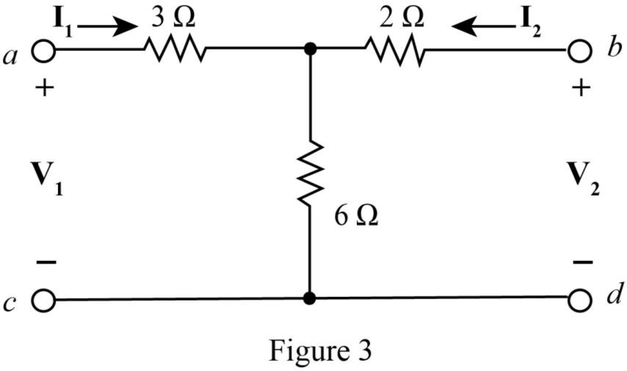
The impedance parameters can be expressed as,
Substitute
Substitute
Substitute
Substitute
Apply KVL left loop of Figure 3.
Substitute
Substitute
Substitute
Substitute
Apply KVL at the right loop.
Substitute
Substitute
Substitute
Substitute
Hence the
Convert the delta connected network to star connected network.
The required diagram is shown in Figure 4.
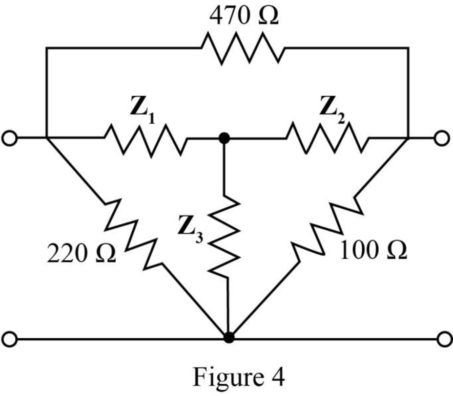
The impedance
The impedance
The impedance
Redraw the star connected circuit.
The required diagram is shown in Figure 5.
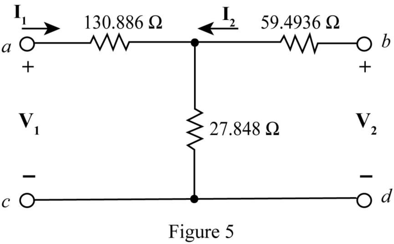
Apply KVL in the left loop.
Substitute
Substitute
Substitute
Substitute
Apply KVL at right loop of Figure 5.
Substitute
Substitute
Substitute
Substitute
The
The overall impedance matrix when the two port networks are connected in series is,
Substitute
Conclusion:
Therefore, the value of total impedance when the two port networks are connected in series is
(b)
The value of admittance parameters for the given condition.
Answer to Problem 35E
The value of total admittance when the two port networks are connected in parallel is
Explanation of Solution
Calculation:
The standard equation for admittance parameters is given by,
Substitute
Substitute
Substitute
Substitute
Modify the given diagram for
The required diagram is shown in Figure 6.
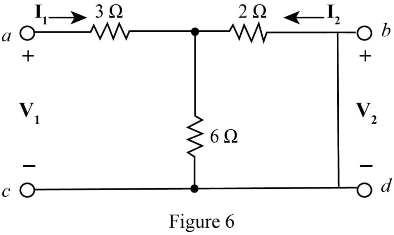
The resistances
The equivalent resistance is,
Further, the resistances
The total equivalent resistance of the circuit is given by,
Substitute
The input voltage calculated from the circuit is written as,
Rearrange the above equation as,
Substitute
Substitute
Rearrange equation (7) as,
Apply current division rule in Figure 6.
Substitute
Substitute
Modify the given diagram for
The required diagram is shown in Figure 7.
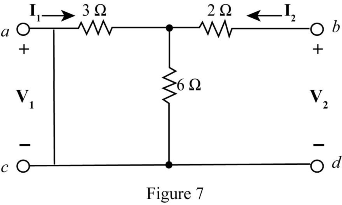
Rearrange equation (8).
Apply current division rule in the circuit of Figure 7.
Substitute
Substitute
The resistances
The equivalent resistance is,
Further, the resistances
The total equivalent resistance of the circuit is given by,
Substitute
The input voltage of Figure 7 can be expressed as,
Rearrange the above equation as,
Substitute
Substitute
The
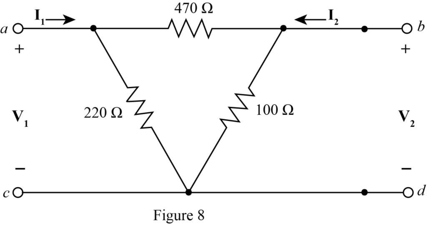
Redraw the Figure 2 and show the input voltage
The required diagram is shown in Figure 8.
Redraw the above figure for
The required diagram is shown in Figure 9.
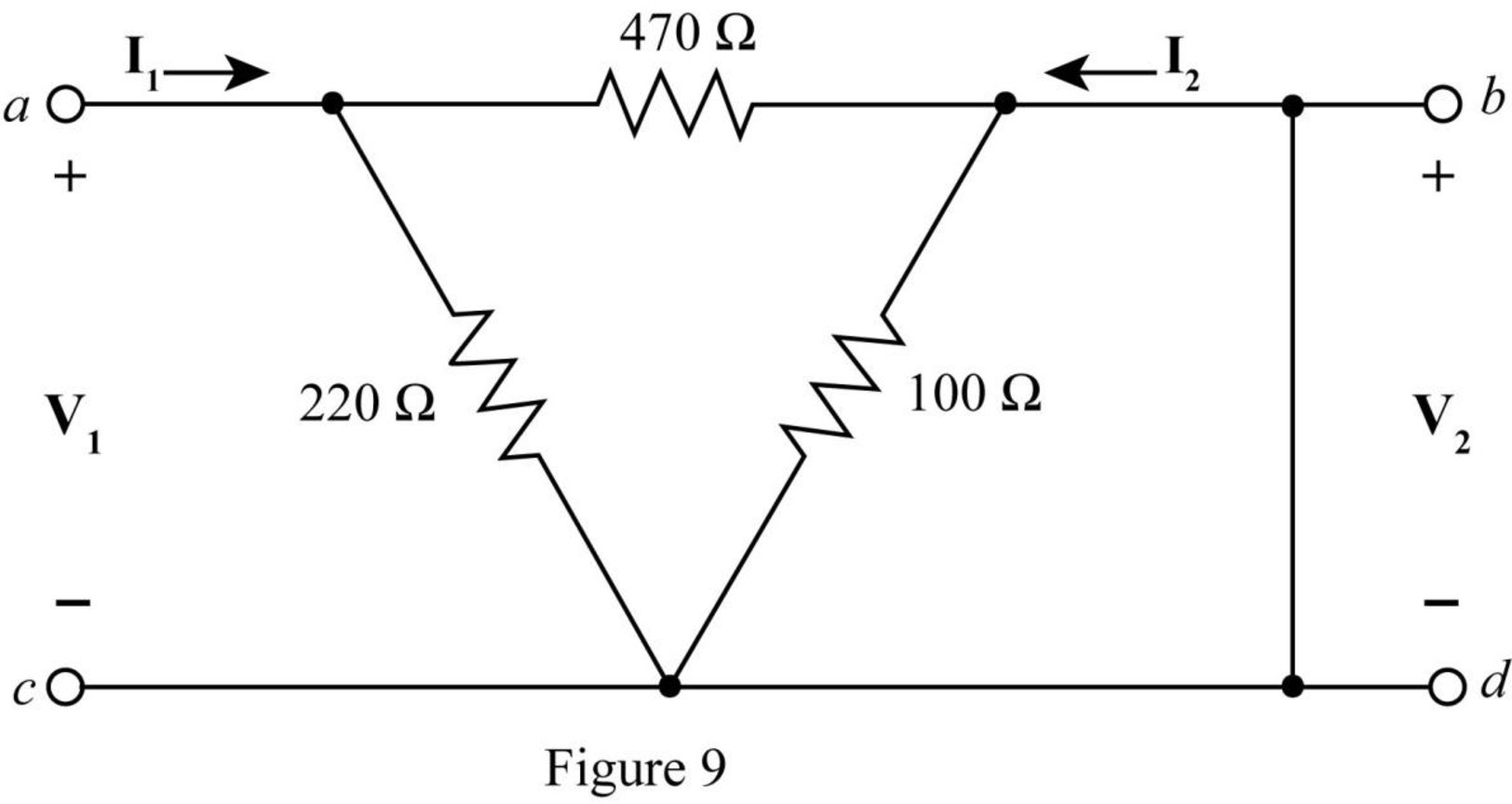
The
Therefore,
The equivalent resistance of the above circuit is,
The input voltage of Figure 9 can be expressed as,
Rearrange the above equation as,
Substitute
Substitute
The voltage across
Therefore, the current through
Rearrange the above equation as,
Substitute
Redraw the above figure for
The required diagram is shown in Figure 10.
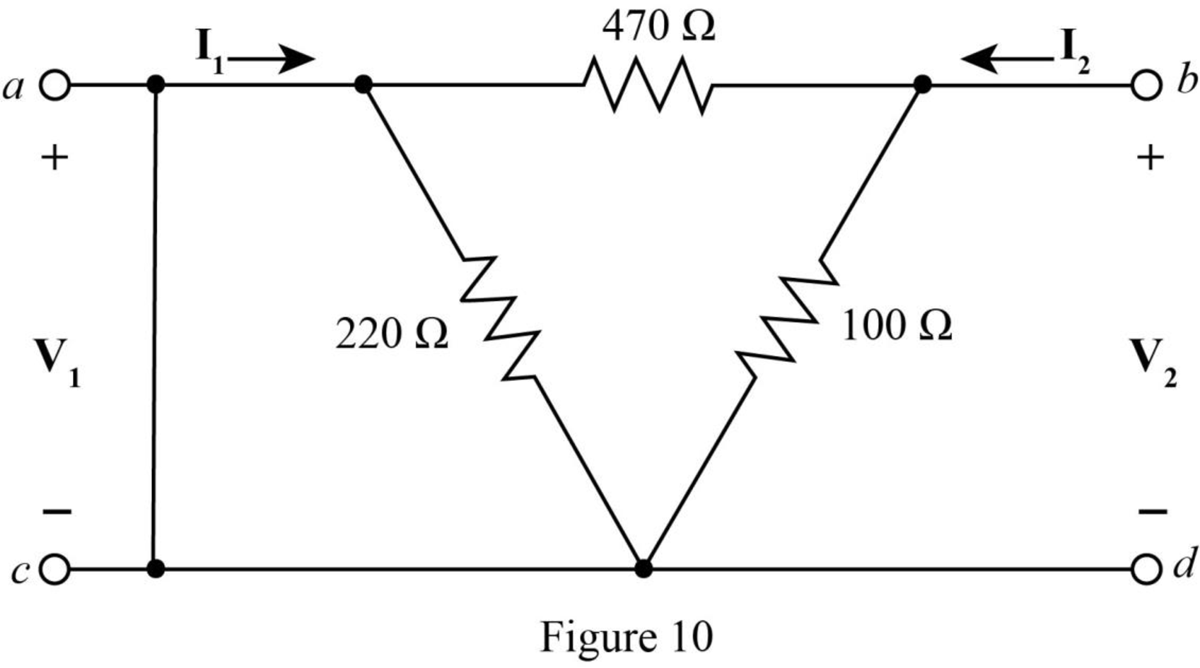
The
The voltage across
Therefore, the current through
Rearrange the above equation as,
Substitute
The
The equivalent resistance of the above circuit is,
The input voltage of Figure 10 can be expressed as,
Rearrange the above equation as,
Substitute
Substitute
The
The overall admittance matrix when the two port networks are connected in parallel is,
Substitute
Conclusion:
Therefore, the value of total admittance when the two port networks are connected in parallel is
(c)
The value of
Explanation of Solution
Calculation:
The determinant of
The matrix for
Substitute
The determinant of
Substitute
Conclusion:
Therefore, the value of
Want to see more full solutions like this?
Chapter 16 Solutions
Loose Leaf for Engineering Circuit Analysis Format: Loose-leaf
Additional Engineering Textbook Solutions
Electric Circuits. (11th Edition)
Principles and Applications of Electrical Engineering
Electric machinery fundamentals
Electrical Engineering: Principles & Applications (7th Edition)
ANALYSIS+DESIGN OF LINEAR CIRCUITS(LL)
Principles Of Electric Circuits


- 1. Implement (2,1,3) convolutional encoder in Fig. 10.12. Give a message vector, u of arbitrary length as input to the encoder.3. Generate the output code sequence.arrow_forwardFind the Y-parameters for the two-port network shown below.arrow_forward8. For reciprocal two-port electrical network, the mutual parameters are.......? a. unequal. b. equal. c. both of them.arrow_forward
- A two-port is described by the following equations: V1 = 50I1 + 10I2 and V2 = 30I1 + 20I2. Which of the following is not true? Z12 = 10 Y12 = -0.0143 h12 = 0.5 B = 50arrow_forwardFind the z parameters for the two-port networkarrow_forwardDetermine the impedance matrix Z(s) of the following 2-port. Assume L1=2 H, L2=3 H, M=1 H, R1=20 Ω, R2=10 Ω,C=2 F.arrow_forward
- Derive the expressions for the h parameters as functions of the gparameters.arrow_forwardFind the S domain Z parameter matrix of the two-port circuit given below.arrow_forwardFind the T-parameters of a two-port device whose Z-parameters are Z11 = 106 s, Z12 = Z21 =107 s, and Z22 = 108 s.arrow_forward
 Power System Analysis and Design (MindTap Course ...Electrical EngineeringISBN:9781305632134Author:J. Duncan Glover, Thomas Overbye, Mulukutla S. SarmaPublisher:Cengage Learning