
ENGINEERING CIRCUIT...(LL)>CUSTOM PKG.<
9th Edition
ISBN: 9781260540666
Author: Hayt
Publisher: MCG CUSTOM
expand_more
expand_more
format_list_bulleted
Videos
Textbook Question
Chapter 16, Problem 29E
Compute the three parameter values necessary to construct an equivalent network for Fig. 16.43 modeled after the network of Fig. 16.13c. Verify their equivalence with an appropriate computer simulation. (Hint: Connect some type of source(s) and load(s).)
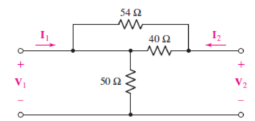
■ FIGURE 16.43
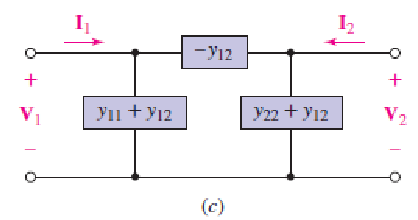
■ FIGURE 16.13
Expert Solution & Answer
Want to see the full answer?
Check out a sample textbook solution
Students have asked these similar questions
If the power system has 'n' number of generators, then the size of the B- coefficient matrix is (nxn).
Select one:
True
False
BUS1
(16) U
BUS2
For the power system with given values, what is the
per unit value of active power at bus -2 only.
(16) U
(12)N
(1+J6) U
V1=1.1200; V2=1.1230°; V3=0.9290°; V4=1.1200
OF
BUS3
(16) U
Bus-4 LOAD
Q4. Use a Karnaugh map to minimize the following standard SOP expression: (15 M)
ABC + ABC + ABC + ABC + ABC
Q5. Plot the corresponding SUM and CARRY outputs of half-adder circuit, for the given A and
B inputs. And give the logical expression for both. (15 M)
HA
A
B
Chapter 16 Solutions
ENGINEERING CIRCUIT...(LL)>CUSTOM PKG.<
Ch. 16.1 - Find the input impedance of the network shown in...Ch. 16.1 - Write a set of nodal equations for the circuit of...Ch. 16.2 - By applying the appropriate 1 V sources and short...Ch. 16.2 - Prob. 4PCh. 16.2 - Prob. 5PCh. 16.3 - Prob. 6PCh. 16.3 - Use Y and Y transformations to determine Rin for...Ch. 16.4 - Find z for the two-port shown in (a) Fig. 16.23a;...Ch. 16.4 - Prob. 9PCh. 16.5 - Prob. 10P
Ch. 16.5 - Prob. 11PCh. 16.6 - Prob. 12PCh. 16 - For the following system of equations, (a) write...Ch. 16 - With regard to the passive network depicted in...Ch. 16 - Determine the input impedance of the network shown...Ch. 16 - For the one-port network represented schematically...Ch. 16 - Prob. 6ECh. 16 - Prob. 7ECh. 16 - Prob. 8ECh. 16 - Prob. 9ECh. 16 - (a) If both the op amps shown in the circuit of...Ch. 16 - Prob. 11ECh. 16 - Prob. 12ECh. 16 - Prob. 13ECh. 16 - Prob. 14ECh. 16 - Prob. 15ECh. 16 - Prob. 16ECh. 16 - Prob. 17ECh. 16 - Prob. 18ECh. 16 - Prob. 19ECh. 16 - Prob. 20ECh. 16 - For the two-port displayed in Fig. 16.49, (a)...Ch. 16 - Prob. 22ECh. 16 - Determine the input impedance Zin of the one-port...Ch. 16 - Determine the input impedance Zin of the one-port...Ch. 16 - Employ Y conversion techniques as appropriate to...Ch. 16 - Prob. 26ECh. 16 - Prob. 27ECh. 16 - Prob. 28ECh. 16 - Compute the three parameter values necessary to...Ch. 16 - It is possible to construct an alternative...Ch. 16 - Prob. 31ECh. 16 - Prob. 32ECh. 16 - Prob. 33ECh. 16 - Prob. 34ECh. 16 - The two-port networks of Fig. 16.50 are connected...Ch. 16 - Prob. 36ECh. 16 - Prob. 37ECh. 16 - Obtain both the impedance and admittance...Ch. 16 - Prob. 39ECh. 16 - Determine the h parameters which describe the...Ch. 16 - Prob. 41ECh. 16 - Prob. 42ECh. 16 - Prob. 43ECh. 16 - Prob. 44ECh. 16 - Prob. 45ECh. 16 - Prob. 46ECh. 16 - Prob. 47ECh. 16 - Prob. 48ECh. 16 - Prob. 49ECh. 16 - Prob. 50ECh. 16 - (a) Employ suitably written mesh equations to...Ch. 16 - Prob. 52ECh. 16 - Prob. 53ECh. 16 - The two-port of Fig. 16.65 can be viewed as three...Ch. 16 - Consider the two separate two-ports of Fig. 16.61....Ch. 16 - Prob. 56ECh. 16 - Prob. 57ECh. 16 - Prob. 58ECh. 16 - (a) Obtain y, z, h, and t parameters for the...Ch. 16 - Four networks, each identical to the one depicted...Ch. 16 - A cascaded 12-element network is formed using four...Ch. 16 - Prob. 62ECh. 16 - Continuing from Exercise 62, the behavior of a ray...
Additional Engineering Textbook Solutions
Find more solutions based on key concepts
Find I0 and I1 in the circuit in Fig.P2.12.
Basic Engineering Circuit Analysis
The current source in the circuit shown generates the current pulse
Find (a) v (0); (b) the instant of time gr...
Electric Circuits. (11th Edition)
A constant voltage of 10V is applied to a 50H inductance, as shown in Figure P3.51 Figure P3 51 The current in ...
Electrical Engineering: Principles & Applications (7th Edition)
Assume a telephone signal travels through a cable at two-thirds the speed of light. How long does it take the s...
Electric Circuits (10th Edition)
Identify the type of input and output configuration for each diff-amp in Figure 18-35.
Electronics Fundamentals: Circuits, Devices & Applications
The voltage source of the circuit shown in Fig. P1.29 is given by s(t)=25cos(4104t45)(V). Obtain an expression ...
Fundamentals of Applied Electromagnetics (7th Edition)
Knowledge Booster


Learn more about
Need a deep-dive on the concept behind this application? Look no further. Learn more about this topic, electrical-engineering and related others by exploring similar questions and additional content below.Similar questions
- find in less than 30 min pls.arrow_forwardQ4. Use a Karnaugh map to minimize the following standard SOP expression: (15 M) ABC + ABC + ABC + ABC + ABC Q5. Plot the corresponding SUM and CARRY outputs of half-adder circuit, for the given A and B inputs. And give the logical expression for both.(15 M) +H Barrow_forwardLet's assume that we have a power system with 1000 buses including 200 generator buses. This system has 1186 transmission lines. If we are planning to use DC power flow to find the flows within this system, what would be the dimensions of the incident matrix (A)? O 1186 x 999 O 1186 x 200 O 200 x 1186 O 199 x 1000arrow_forward
- Consider the following sub_module_verilog code: module sub-module-verilog (input A, B, output wire M,N,S); Assign M A-^B; Assign NA & -B; Assign SA & B; endmodule Consider the following main_module_verilog code: module main-module-verilog (input wire [2:0] A, B, output wire X, Y, Z); wire so, s1, 52, 53, 54, 55, 56, 57, 58; sub-module-verilog eq_bito (.A (A[0]), B(B[0]), .M(SO), .N(s1), S(s2)); sub-module-verilog eq_bit1 (.A (A[1]), B(B[1]), .M(53), .N (34), S(s5)); sub-module-verilog eq_bit2 (.A (A[2]), B(B[2]), .M(56), .N(57), .S(58)); assign X 50 & 33 & 36; assign Y s7 | (56 & 54) | (56 & 53 & 51); assign Z s8 | (s6 & s5) | (56 & 53 & 52); endmodule The module described above represents 3-bit binary to gray code converter 3-bit parity generator 3-bit magnitude comparator None of the abovearrow_forwardA single phase Cycloconverter, if the input supply voltage is Vs= 220 V with frequency (f= 50 Hz) and the trigger angle (a= 45°), the conduction angle (0=168°) and the load is (R=10 2 in series with L= 18.377 mH). Then determine the followings:- I 1) Draw the Cycloconverter circuit. 2) Determine the value of load angle (Þ). 3) Determine the value of the commutation angle (3). 4) Draw to scale the input voltage and current, the output voltages and the current waveforms. 5) Determine the mean and rms values of the output voltage.arrow_forward57 AF Microsoft Word (Product Activation Failed) Table Tools References Mailings Review View Design Layout 12 AA Aa- =,=,年| AaBbCcDc AaBbCcDc AaBbC AaBbCc Ac = X, x' ab - 1 Normal I No Spaci.. Heading 1 Heading 2 Ti Font Paragraph Styles Q6. A line charging admittance of Y bus matrix is connected between two buses its affect at each bus is consider as Ofull O None of the above Half of the total Averagearrow_forward
- In a DC optimal power flow problem of 3 bus network. The flow on lines was found to as follow: f12=100 M, MW, f13=150 MW, and f23 =120MW. The lines limits are 140 MW each. and the system base MVA =10OMVA. What additional constraint to be added on the solution of the DCOPF Select one: O a. None of these O b. 100 (0, - 02)/x12= 150 Oc. 100 (0, - 03)/x13= 140 O d. 100 (0, - 03)/x13= 160 O e. 100 (0, - 03)/x13= 130 O f. 100 (0, - 03)/x13= 150arrow_forwardFor calculating the Thevenin's Equivalent Resistance(RIh) at load terminals, remove the load resistance and if a voltage soure by a short circuit and a current source is replaced by an open circuit source is present replaced by an open circuit A_ True B_Falsearrow_forwardSolve 4arrow_forward
- c) Two power system transmission engineers designed a transmission system. One used the lumped parameters and the other used distributed parameters in their transmission line analysis. Could you kindly evaluate the differences of these parameters chosen by the two engineers?arrow_forwardCalculate the thermal load associated with a change in temperature equal to +/- 20 for a bridge. The bridge has span 171.74m ans 90m in height, and is located in Genoa Italy.arrow_forwardThe Jacobian matrix has all the four elements, if a PQ bus is connected to another PV bus.Select one:O TrueO Falsearrow_forward
arrow_back_ios
SEE MORE QUESTIONS
arrow_forward_ios
Recommended textbooks for you
 Power System Analysis and Design (MindTap Course ...Electrical EngineeringISBN:9781305632134Author:J. Duncan Glover, Thomas Overbye, Mulukutla S. SarmaPublisher:Cengage Learning
Power System Analysis and Design (MindTap Course ...
Electrical Engineering
ISBN:9781305632134
Author:J. Duncan Glover, Thomas Overbye, Mulukutla S. Sarma
Publisher:Cengage Learning
L21E127 Control Systems Lecture 21 Exercise 127: State-space model of an electric circuit; Author: bioMechatronics Lab;https://www.youtube.com/watch?v=sL0LtyfNYkM;License: Standard Youtube License