
Concept explainers
Videos
15.113 and 15.114 A 3-in.-radius drum is rigidly attached to a 5-in.- radius drum as shown. One of the drums rolls without sliding on the surface shown, and a cord is wound around the other drum. Knowing that at the instant shown end D of the cord has a velocity of 6 in./s and an acceleration of 20 in./s2, both directed to the right, determine the accelerations of points A, B, and C of the drums.
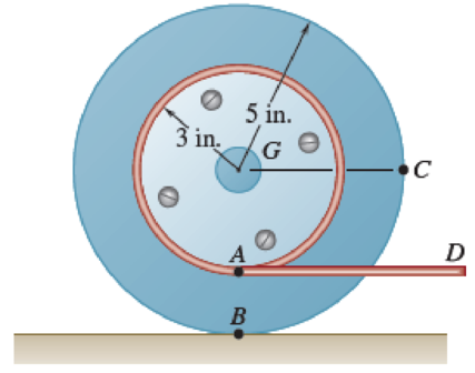
Fig. P15.113
Want to see the full answer?
Check out a sample textbook solution
Chapter 15 Solutions
VEC MECH 180-DAT EBOOK ACCESS(STAT+DYNA)
Additional Engineering Textbook Solutions
Vector Mechanics for Engineers: Statics, 11th Edition
Manufacturing Engineering & Technology
Vector Mechanics for Engineers: Dynamics
Automotive Technology: Principles, Diagnosis, and Service (5th Edition)
Engineering Mechanics: Statics & Dynamics (14th Edition)
Thinking Like an Engineer: An Active Learning Approach (3rd Edition)


- A 3-in.-radius drum is rigidly attached to a 5-in.-radius drum as shown. One of the drums rolls without sliding on the surface shown, and a cord is wound around the other drum. Knowing that at the instant shown. point A has a velocity of 5.75 in./s and an acceleration of 19 in./s2, both directed to the right, determine the accelerations of points A, B, and C of the drums. a) The accelerations of point B is _ upward? b) The accelerations of point A is _ and _? (magnitude and direction) c) The accelerations of point C is _ and _? (magnitude and direction)arrow_forward15.115 and 15.116 A 60-mm-radius drum is rigidly attached to a 100-mm-radius drum as shown. One of the drums rolls without sliding on the surface shown, and a cord is wound around the other drum. Knowing that at the instant shown end D of the cord has a velocity of 160 mm/s and an acceleration of 600 mm/s², both directed to the left, determine the accel- erations of points A, B, and C of the drums. a D 100 mm G 60 mm 40 B Carrow_forwardProblem (8) The belt shown moves over two pulleys without slipping. At the instant shown the pulleys are rotating clockwise and the speed of point B on the belt is 4 m/s, increasing at the rate of 32 m/s?. Determine, at this instant, (a) the angular velocity and angular acceleration of each pulley, (b) the acceleration of point P on pulley C. B 160 mm fi00 mmarrow_forward
- 15.113 The 360-mm-radius flywheel is rigidly attached to a 30-mm- radius shaft that can roll along parallel rails. Knowing that at the instant shown the center of the shaft has a velocity of 24 mm/s and an acceleration of 10 mm/s, both directed down to the left, determine the acceleration (a) of point A, (b) of point B. A 2₂x 360 mm- 20° Barrow_forward6) Bar BDE is attached to two links AB and CD. Knowing that at the instant shown link AB rotates with a constant angular velocity of 3 rad/s clockwise, determine the acceleration (a) of point D, (b) of point E. 19.1 cm 19.1 cm C -30.5 cm -22.9 cm- B ODarrow_forwardA carriage c is supported by a caster A and a cylinder B each of 60 mm diameter. Knowing that at an instant the carriage has an acceleration of 3 m/s^2 and a velocity of 2 m/s , both directed to the left , calculate the angular accelerations of the caster and of the cylinder then calculate the accelerations of the centers of the caster and of the cylinder?arrow_forward
- Required information NOTE: This is a multi-part question. Once an answer is submitted, you will be unable to return to this part. For a 5-m steel beam AE, the acceleration of point A is 2.5 m/s² downward and the angular acceleration of the beam is 1.5 rad/s2 counterclockwise. Knowing that at the instant considered the angular velocity of the beam is zero, determine the acceleration of cable B and cable D. A -1.5 m- B Determine the acceleration of cable B The acceleration of cable Bis 2 m 1.375 5 m/s2. D -1.5 m- Earrow_forwardProblem (1) A belt-driven pulley and attached disk are rotating with increasing angular velocity. If at a given instant, the speed of the belt is v = 1.5 m/s, and the total acceleration of point A is 100 m/s?, determine: (a) The angular acceleration a of the pulley and disk (b) The total acceleration of point B (c) The acceleration of point C on the belt. A 150 mm 200 mmarrow_forward3. The 80-mm-radius wheel shown rolls without slipping to the left with a velocity of 900 mm/s. Knowing that the distance AD is 50 mm, determine the velocity of the collar and the angular velocity of rod AB when (a) 0 = 0, (b) 0 = 90°. %3D fixed rod B - 80 mm- D 250 mm 160 mmarrow_forward
- A The 18-in.-radius fly wheel is rigidly attached to a 1.5-in. -radius shaft that can roll along parallel rails. Knowing that at the instant shown the center of the shaft has a velocity of 1.2 in/s and an acceleration of 0.5 in/s?, both directed down to the left, determine the acceleration (a) of point A, (b) of point B. 18 in. 20 Вarrow_forwardThe 200-mm-radius disk rolls without sliding on the surface shown. Knowing that the distance BG is 160 mm and that at the instant shown the disk has an angular velocity of 5.50 rad/s counterclockwise and an angular acceleration of 7.00 rad/s² clockwise, determine the acceleration of A. A 730 mm 200 mm Barrow_forwardA circular plate of 120-mm radius is supported by two bearings A and B as shown. The plate rotates about the rod joining A and B with a constant angular velocity of 26 rad/s. Knowing that, at the instant considered, the velocity of point C is directed to the right, determine the velocity and acceleration of point E.arrow_forward
 Elements Of ElectromagneticsMechanical EngineeringISBN:9780190698614Author:Sadiku, Matthew N. O.Publisher:Oxford University Press
 Mechanics of Materials (10th Edition)Mechanical EngineeringISBN:9780134319650Author:Russell C. HibbelerPublisher:PEARSON
 Thermodynamics: An Engineering ApproachMechanical EngineeringISBN:9781259822674Author:Yunus A. Cengel Dr., Michael A. BolesPublisher:McGraw-Hill Education
 Control Systems EngineeringMechanical EngineeringISBN:9781118170519Author:Norman S. NisePublisher:WILEY
 Mechanics of Materials (MindTap Course List)Mechanical EngineeringISBN:9781337093347Author:Barry J. Goodno, James M. GerePublisher:Cengage Learning
 Engineering Mechanics: StaticsMechanical EngineeringISBN:9781118807330Author:James L. Meriam, L. G. Kraige, J. N. BoltonPublisher:WILEY