Calculate all the reactions and draw the moment diagrams.
Answer to Problem 6P
The vertical reaction at A is
The vertical reaction at B is
The vertical reaction at C is
The bending moment at A is
The bending moment at B is
The bending moment at C is
Explanation of Solution
Restrained structure: Clamp joint 2:
Show the free body diagram of the restrained structure as in Figure (1).
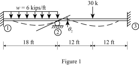
Refer Figure (1),
Find the fixed end moment of the member 1-2
Find the fixed end moment of the member 2-3
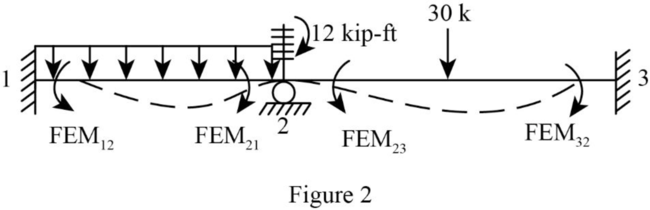
Find the moment in clamp using the relation;
Show the free body diagram of the restrained structure with FEM and moment as in Figure (2).
Show the free body diagram of the structure with unit rotation at 2 Figure (3).
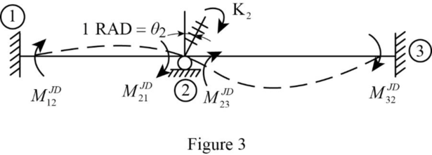
Moments due to unit rotation at 2:
Find the moment at the member 1-2 using the relation;
Find the moment at the member 2-1 using the relation;
Find the moment at the member 2-3 using the relation;
Find the moment at the member 3-2 using the relation;
Find the stiffness coefficient
Find the rotation at joint 2;
Take summation moment about joint 2.
Find the moment at the member 1-2 using the relation;
Find the moment at the member 2-1 using the relation;
Find the moment at the member 2-3 using the relation;
Find the moment at the member 3-2 using the relation;
Show the free body diagram of the beam as in Figure (4).
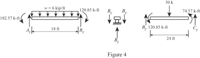
Refer Figure (4),
Consider AB:
Find the vertical reaction at A;
Take summation moment about B.
Thus, the vertical reaction at A is
Find the vertical reaction at B;
Summation of forces about y axis is equal to zero.
Consider BC:
Find the vertical reaction at B;
Take summation moment about C.
Find the vertical reaction at C;
Summation of forces about y axis is equal to zero.
Thus, the vertical reaction at C is
Find the total vertical reaction at B;
Thus, the vertical reaction at B is
Show the free body diagram of the beam as in Figure (5).
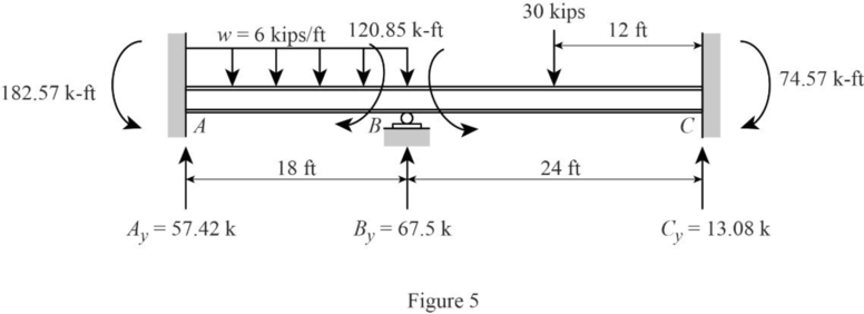
Refer Figure (5),
Shear force calculation:
Find the distance when shear force is zero (x):
Equate the equation of shear force to zero.
Bending moment calculation:
Thus, the bending moment at A is
Thus, the bending moment at B is
Thus, the bending moment at C is
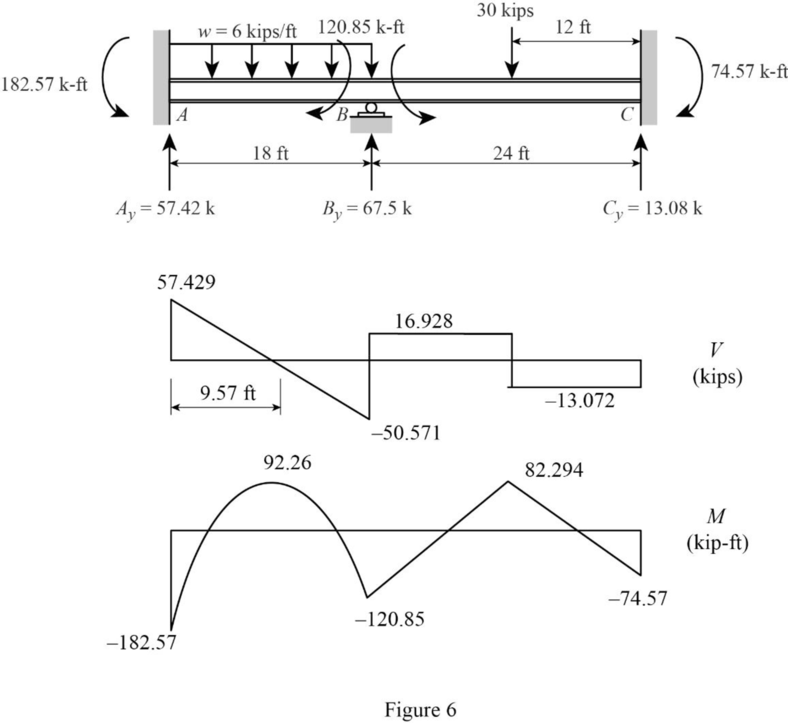
Show the shear force and bending moment diagram as in Figure (6).
Want to see more full solutions like this?
Chapter 14 Solutions
Connect Access Card For Fundamentals Of Structural Analysis (one Semester Access) 5th Edition


 Structural Analysis (10th Edition)Civil EngineeringISBN:9780134610672Author:Russell C. HibbelerPublisher:PEARSON
 Principles of Foundation Engineering (MindTap Cou...Civil EngineeringISBN:9781337705028Author:Braja M. Das, Nagaratnam SivakuganPublisher:Cengage Learning
 Fundamentals of Structural AnalysisCivil EngineeringISBN:9780073398006Author:Kenneth M. Leet Emeritus, Chia-Ming Uang, Joel LanningPublisher:McGraw-Hill Education
 Traffic and Highway EngineeringCivil EngineeringISBN:9781305156241Author:Garber, Nicholas J.Publisher:Cengage Learning