Concept explainers
Using excel, plot the graph shows the deflection of a beam and also calculate the maximum deflection of the beam.
Answer to Problem 12P
Using excel, a table and graph is created to shows the deflection of a beam and the maximum deflection of the beam is
Explanation of Solution
Given data:
The length of the cantilever beam is
The modulus of elasticity
That is,
The second moment of area
That is,
The distributed load
Formula used:
Formula to calculate the deflection of the cantilever of the beam is,
Here,
Calculation:
Consider the distance (x) from the support as shown with the range from
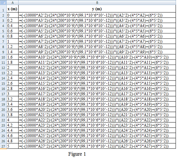
Refer to the Figure 1:
Column A shows the distance
Column B shows the deflection
Here, A2 cell represent the distance
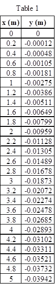
Table 1 shows the distance
Refer to the Figure 14.16 in the textbook.
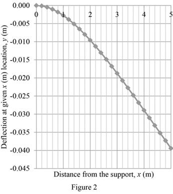
Draw the graph for the distance
For X-axis, scale change is done by clicking the Layout on toolbar and picks the “Axes”. Choose the primary horizontal axis and select the “More Primary Horizontal Axis Options”. A dialog box of Format axis shows the axis option in that click the fixed and type the minimum value as 0, maximum value as 5, and major unit as 1 and minor unit as 0.2 and click the close option.
Likewise for Y-axis, scale change is done by clicking the Layout on toolbar and picks the “Axes”. Choose the primary vertical axis and select the “More Primary Vertical Axis Options”. A dialog box of Format axis shows the axis option in that click the fixed and type the minimum value as
Figure 2 shows the curve of the deflection of a cantilever beam.
For the maximum deflection of the beam, the distance
That is,
Given,
Substitute the unit
Substitute
Thus, the maximum deflection of the beam is
Conclusion:
Hence, a table and graph is created using excel to shows the deflection of a beam and the maximum deflection of the beam is
Want to see more full solutions like this?
Chapter 14 Solutions
ENGINEERING FUNDAMENTALS


- (Figure 1) Figure 30 mm 140 mm, 30 mm 30 mm 70 mm 30 mm 170 mm 1 of 1 Part A Determine the distance to the centroid C of the beam's cross-sectional area. Express your answer to three significant figures and include the appropriate units. X = Submit Part B Īy = Value μA Submit < Return to Request Answer Compute the moment of inertia Iy about the y' axis. Express your answer to three significant figures and include the appropriate units. Value Request Answer Units ignment Units ? Provide Feedback ?arrow_forwardConsider a beam shown in the figure below. (Figure 1) Figure 1 ▾of 1 400 lb/ft 6 ft 900 lb Part A Express the internal shear in terms of x for 0≤x≤6 ft, where is in ft. Express your answer in terms of z. Express your answer using three significant figures. V= Submit V= ΑΣΦΗ ΤΗ Submit vec My Answers Give Up [VD ΑΣΦ | 4 Part B Express the internal shear in terms of z for 6 ft << 9 ft, where is in ft. Express your answer in terms of z. Express your answer using three significant figures. vec ? My Answers Give Up lb ? lbarrow_forwardSuppose we have a uniform beam that is 3.73 metres long has a flexural rigidity of 34301Nm. Find the deflection of the beam in millimetres if the beam is under a uniform load of 86N/m and is supported with simple supports at both ends. Fill out the table below with your answers. x�-coordinate Deflection (mm��) x=0.22 y(x)= x=1.38 y(x) = x=2.05 y(x) = x=2.98 y(x) = x=3.58 y(x) = Enter as many decimal places as your calculator allows (8 to 10). Your answer must be within ±0.0005±0.0005 of the correct answer to be considered correct.arrow_forward
- Consider a stepped shaft subjected to a twisting moment applied at B as shown in the figure. Assume shear modulus, G = 77 GPa. The angle of twist at C (in degrees) is (Give answer up to three decimal places) All dimensions 10 Nm in mm $20 500 B 44 S $10 500 Carrow_forwardSuppose we have a uniform beam that is 3.40metres long has a flexural rigidity of 31915N Find the deflection of the beam in millimetres if the beam is under a uniform load of 24Nmand is supported with simple supports at both ends. Fill out the table below with your answers. x�-coordinate Deflection (mm��) x=0.14 y(x)�(�) = x=1.12 y(x)�(�) = x=1.80 y(x)�(�) = x=2.65 y(x)�(�) = x=3.06 y(x)�(�) = Enter as many decimal places as your calculator allows (8 to 10). Your answer must be within ±0.0005±0.0005 of the correct answer to be considered correct.arrow_forwardConsider a beam shown in the figure below. (Figure 1) Figure 1 ▼ of 1 400 lb/ft 6 ft 900 lb Part A Express the internal shear in terms of a for 0≤x≤6 ft, where x is in ft. Express your answer in terms of z. Express your answer using three significant figures. V= Submit V= V ΑΣΦ | Η Submit vec My Answers Give Up [VD ΑΣΦ | 41 Part B Express the internal shear in terms of x for 6 ft << 9 ft, where is in ft. Express your answer in terms of z. Express your answer using three significant figures. vec ? My Answers Give Up lb ? lbarrow_forward
- Consider the beam shown in (Figure 1). Suppose that a = 160 mm, b=210 mm, c= 50 mm. Figure 1 of 1 a a Part A Determine the moment of inertia of the beam's cross-sectional area about the centroidal z axe. Express your answer to three significant figures and include the appropriate units. I₂ = Submit Part B Iy= μA Submit Value Determine the moment of inertia of the beam's cross-sectional area about the centroidal y axe. Express your answer to three significant figures and include the appropriate units. Units My Answers Give Up μA Value Units ? My Answers Give Up ? Provide Feedback Continuearrow_forward9. If a load of 60 kN is applied to a rigid bar suspended by 3 wires as shown in the above figure what force will be resisted by each wire? The outside wires are of Al, cross- sectional area 300 mm² and length 4 m. The central wire is steel with area 200 mm² and length 8 m Initially there is no slack in the wires E= 2x10⁵ N/mm² for Steel = 0.667x10⁵ N/mm2 for Aluminum 60 kN Alum, wires Steel wirearrow_forwardQuestion 3: Open Ended The beam in the following diagram has the following numerical values in stiffness: 77 Stiffness in bending = 1 Stiffness in axial tension = 1 What would the new values of stiffness in bending and axial tension be if the Height of beam is doubled while the Width remains constant? What would the new values of stiffness in bending and axial tension be if the Width of beam is doubled while the Height remains constant?arrow_forward
- Part D - Analyzing a system of forces acting on a concrete slab The concrete slab shown in the picture is subject to four forces, F1=125 lb, F2=260 lb, F3=675 lb, and F4=255 lb. (Figure 3) The dimensions are d1=8.0 ft, d2=24 ft, d3=3.0 ft, d4=13 ft, and d5=9.5 ft. Determine the equivalent resultant force by specifying its magnitude and its location (x,y) on the slab. Express your answers, separated by commas, to three significant figures. FR, x, y= lb, ft,ftarrow_forward4. a) Determine an expression for the deflection of the left end of the beam shown. b) If a = 100 cm, P = 2200 N, w = 2600 N/m, M = 1500 N·m, E = 200 GPa, and I = 15 x 106 mm4, calculate the deflection of the free end of the beam M a w a www/warrow_forward1. The following equation describes the relationship between the maximum deflection of the end of a beam and the applied load. PL3 = 3EI a) If ð is the maximum deflection in inches, L is the length of the beam in inches, P is the load in pounds, and E is the Young's Modulus in pounds/in?, find the units for I (moment of inertia). b) The measured deflection for a specific beam under loading is measured to be .01 in. Convert this to millimeters.arrow_forward

 Structural Analysis (10th Edition)Civil EngineeringISBN:9780134610672Author:Russell C. HibbelerPublisher:PEARSON
 Principles of Foundation Engineering (MindTap Cou...Civil EngineeringISBN:9781337705028Author:Braja M. Das, Nagaratnam SivakuganPublisher:Cengage Learning
 Fundamentals of Structural AnalysisCivil EngineeringISBN:9780073398006Author:Kenneth M. Leet Emeritus, Chia-Ming Uang, Joel LanningPublisher:McGraw-Hill Education
 Traffic and Highway EngineeringCivil EngineeringISBN:9781305156241Author:Garber, Nicholas J.Publisher:Cengage Learning