
Concept explainers
Videos
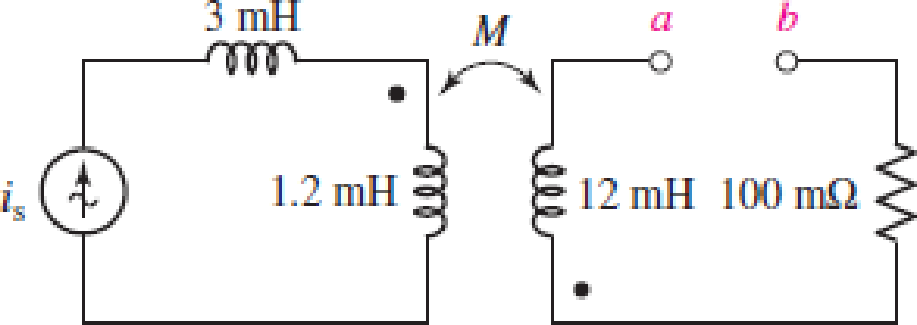
Consider the circuit represented in Fig. 13.53. The coupling coefficient k = 0.75. If is = 5 cos 200t mA, calculate the total energy stored at t = 0 and t = 5 ms if (a) a-b is open-circuited (as shown); (b) a-b is short-circuited.
FIGURE 13.53
(a)
Find the total energy stored in the system at
Answer to Problem 27E
The total energy stored in the system at
Explanation of Solution
Given data:
Refer to Figure 13.53 in the textbook for the given circuit.
The terminals a-b in the given circuit are open circuited.
Formula used:
Write the expression for energy stored in the magnetic field due to self-inductance of the coil at an instant of time as follows:
Here,
Calculation:
As the terminals a-b in the given circuit are open circuited, the current through the secondary winding loop is 0 A. Therefore, the total energy stored in the system is only due to the primary coils of the given circuit.
From the given circuit, find the value of inductance of primary coil when the terminals a-b in the given circuit are open circuited as follows:
Find the current through the primary coil at
Modify the expression in Equation (1) for energy stored in the system due to the coil
Substitute
Find the current through the primary coil at
Modify the expression in Equation (1) for energy stored in the system due to the coil
Substitute
Conclusion:
Thus, the total energy stored in the system at
(b)
Find the total energy stored in the system at
Answer to Problem 27E
The total energy stored in the system at
Explanation of Solution
Given data:
The terminals a-b in the given circuit are short-circuited.
Formula used:
Write the expression for energy stored in the magnetic field due to mutual inductance of the coils at an instant of time as follows:
Here,
Write the expression for mutual inductance in terms of self-inductance of primary and secondary coils as follows:
Here,
Calculation:
Substitute
From the given circuit, find the current
Substitute
Simplify the expression as follows:
Find the current through the secondary coil at
From Part (a), the energy stored in the system due to the coil
Modify the expression in Equation (1) for energy stored in the system due to the coil
Substitute
Rearrange the expression in Equation (2) to find the energy stored in the magnetic field due to the mutual inductance of the coils at
Substitute
Write the expression for total energy stored in the system at
Substitute
From Part (a), the energy stored in the system due to the coil
Find the current through the secondary coil at
Modify the expression in Equation (1) for energy stored in the system due to the coil
Substitute
Rearrange the expression in Equation (2) to find the energy stored in the magnetic field due to the mutual inductance of the coils at
Substitute
Modify the expression in Equation (4) for total energy stored in the system at
Substitute
Conclusion:
Thus, the total energy stored in the system at
Want to see more full solutions like this?
Chapter 13 Solutions
Loose Leaf for Engineering Circuit Analysis Format: Loose-leaf


- Explore the challenges and benefits of implementing power electronics-based grid solutions like STATCOM (Static Synchronous Compensator) for voltage control and stability.arrow_forwardCalculate the energy stored in the coupled coils at t = 10 ms if M = 0.2 H and vs = 12 cos 10t V.arrow_forwardA resistor of 50 ohms, a 200mH inductor, and a 1.5 x 10⁻⁴ F capacitor are connected in parallel to a 120-volt, 60 cps source. Calculate: a) the total real, reactive, and apparent powers; b) power factor.arrow_forward
- A 10 kVA, 500/250 V, single phase transformer has its maximum efficiency of 94% when delivering 90% of its rated output at unity p.t. Estimate its efficiency when delivering its full load output at p.t. of 0.8 lagging.3arrow_forwardAn Electrical engineer is asked by a client to prepare a technical specification on specific items connected with a project. Hence, the engineer is requested to prepare the technical specification of the following: PROJECT: A Subdivision Development Lot AREA; 2 Hectares LOCATION: Brgy. Kanlurang Mayao, Lucna City Technical specification of fuse cutout Technical specification of transformerarrow_forwardDESIGN A CONVENTIONAL POWER SUPPLY USING 220V AC , 10 KILO OHMS RESISTOR ,4 SILICON DIODES, CAPACITOR , TRANSFORMER WITH 20:1 TURNS' RATIO AND PERCENTAGE ERROR= 5 PERCENT. FIND THE SUITABLE REGULATORarrow_forward
- The following parameters are used in an EDM process, the supply voltage is 150V. The resistance and capacitance in the circuit are 50 Ohms and 15 microfarads respectively. The tool is made of brass and kerosene is used as the dielectric. A hole diameter of 20 mm is to be cut into a plate of thickness of 3mm. If the discharge takes place at maximum power conditions. The value of constant K4=0.18, calculate the MRR, and machining time.arrow_forward"A single coil 800 turns instrument transformer, operating in the step-downs mode with a 25 percent tap, supplies a 10 kVA, 0.80 power factor lagging load. The input to the transformer is 6600 V, 50 Hz. Assume that leakage effects and minor losses in transformer are negligible. Determine the following : (i) Turn ratio; (ii) Load current(in Amp); (iii) Incoming line current(in Amp); (iv) Transformed current (in Amp); (v) Apparent power conducted(in kVA)and (vi) Apparent power transformed"arrow_forwardTwo coupled coils have inductance of L1 = 0.8 H and L2 = 0.2 H, respectively. If the coefficient of coupling is 0.75, find the turns ratio N1/N2 for the coils. Show Solution Pleasearrow_forward
- Electrical engineering A 375 kVA, 6600/400 V, 3-phase core type transformer has a total loss of 3700 watts on full load. The transformer tank is 1.25 m in height and 1 m × 0.5 m in plan. Design a suitable scheme for cooling tubes if the average temperature rise is to be limited to 35 °C. The diameter of the tube is 50 mm and are spaced 75 mm from each other. The average height of the tube is 1.05 m.arrow_forwardPlease Solve ASPS. A 100 kVA, 2000/400 V, 50 Hz, single phase shell type transformer has sandwitch coils. There are two full HIV coils, one full LV coil and two half LV colls. Calculate the value of leakage reactance referred to HV side if the other data given is, depth of HV coil = 4 cm depth of LV coil = 3.6 cm depth of duct between IIV and LV= 1.6 cm width of winding 12 cm length of mean turns = 150 cm HV winding turns = 200 Also calculate the per unit reactance.arrow_forwardGiven a 115kV/13.2kV distribution transformer rated at 30MVA with an 8% nameplate impedance what is the full Load current in ampsarrow_forward
 Introductory Circuit Analysis (13th Edition)Electrical EngineeringISBN:9780133923605Author:Robert L. BoylestadPublisher:PEARSON
 Delmar's Standard Textbook Of ElectricityElectrical EngineeringISBN:9781337900348Author:Stephen L. HermanPublisher:Cengage Learning
 Programmable Logic ControllersElectrical EngineeringISBN:9780073373843Author:Frank D. PetruzellaPublisher:McGraw-Hill Education
 Fundamentals of Electric CircuitsElectrical EngineeringISBN:9780078028229Author:Charles K Alexander, Matthew SadikuPublisher:McGraw-Hill Education
 Electric Circuits. (11th Edition)Electrical EngineeringISBN:9780134746968Author:James W. Nilsson, Susan RiedelPublisher:PEARSON
 Engineering ElectromagneticsElectrical EngineeringISBN:9780078028151Author:Hayt, William H. (william Hart), Jr, BUCK, John A.Publisher:Mcgraw-hill Education,