
Electrical Engineering: Principles & Applications (7th Edition)
7th Edition
ISBN: 9780134484143
Author: Allan R. Hambley
Publisher: PEARSON
expand_more
expand_more
format_list_bulleted
Concept explainers
Videos
Textbook Question
Chapter 13, Problem 13.9P
Consider the circuit shown m Figure P13.9 Sketch
to scale versus time. The op amp is ideal.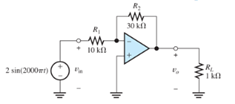
Figure P13.9
Expert Solution & Answer
Want to see the full answer?
Check out a sample textbook solution
Students have asked these similar questions
Find an expression for the output voltage v, below. Assume an ideal op-amp.
What mathematical operation does the circuit perform?
R2
R
V₁2
R₂
R₂
R₁
What do you call this OP-AMP configuration?
Derive its output expression, If Rf=2k and R1=R2=R3=1k2, what is Vo?
An op amp has a maximum output voltage range from -10 to +10 V. The maximum output current magnitude is 25 mA. The slew-rate limit is 1 V/μs. The op amp is used in the amplifier shown in FigureP13.61 . a. Find the full-power bandwidth of the op amp. b. For a frequency of 5 kHz and RL=100 Ω, what peak output voltage is possible without distortion? c. For a frequency of 5 kHz and RL=10 kΩ, what peak output voltage is possible without distortion? d. For a frequency of 100 kHz and RL=10 kΩ, what peak output voltage is possible without distortion?
Chapter 13 Solutions
Electrical Engineering: Principles & Applications (7th Edition)
Knowledge Booster


Learn more about
Need a deep-dive on the concept behind this application? Look no further. Learn more about this topic, electrical-engineering and related others by exploring similar questions and additional content below.Similar questions
- Q1: Choose the correct answer for the following: The terminal number eight for the op amp is considered one of the important terminals. (T or F) • The output section of the nonideal op amp consists of............. (output resistance or output voltage) The output of the first stage in cascaded op amp represents the input of the second stage. (T or F) . ● The first-order circuits can be analyzed by applying. (Kirchhoff's laws or Ohm's law) . The main objective of the source free RL circuit is to find the....... (circuit response or output voltage) ● ● The voltage response of RC circuit decreases while the time increases. (T or F) One of the ways used to excite the RLC circuits is ............. (connected de source or disconnected de source) • Finding the derivatives of initial conditions for second-order circuits are considered......... (major objective or major problem) D CO= = C=Carrow_forwardTRUE/FALSE QUIZ Answers can be found at www.pearsonhighered.com/floyd. 1. An ideal op-amp has an infinite input impedance. 2. An ideal op-amp has a very high output impedance. 3. The op-amp can operate in both the differential mode or the common mode. 4. Common-mode rejection means that a signal appearing on both inputs is effectively cancelled. 5. CMRR stands for common-mode rejection reference. 6. Slew rate determines how fast the output can change in response to a step input. 7. Negative feedback reduces the gain of an op-amp from its open-loop value. 8. Negative feedback reduces the bandwidth of an op-amp from its open-loop value. 9. A noninverting amplifier uses negative feedback. 10. The gain of a voltage-follower is very high. 11. Negative feedback affects the input and output impedances of an op-amp. 12. A compensated op-amp has a gain roll-off of -20 dB/decade above the critical frequency. 13. The gain-bandwidth product equals the unity-gain frequency. 14. If the feedback…arrow_forwardSolve it op amp...arrow_forward
- R2 1 vo Oxford University Publishing Microelectronic Circuits by Adel S. Sedra and Kenneth C. Smith (0195323033) For the op-amp circuit above and given R1 = 10 Ohm, R2 = 5 Ohm, if the DC gain of the op-amp is only 10 (A = 10), what is the output voltage for an input voltage of 0.5V? [Give your answer in number form, no units, no unit prefixes, no commas. Answer to 3 decimal places. Be sure to include negative sign in front, if required Example: 10mV--> Answer Given: 0.010] + 3.arrow_forwardDraw the circuit diagram of a differential amplifier using one op amp and resistances as needed. Give the output voltage in terms of the input voltages and resistances.arrow_forwardDesign of op amp circuit Find the value ofC2. ( need handwritten only ,otherwise downvote.)arrow_forward
- I want the answer with details as soon as possible. Please Q-Design an op-amp circuit to amplify the AC voltage of 0.7v to become 3v , And the voltage of VCC is 5v DC.arrow_forwardAn op amp has a gain of 100 dB at dc and a unity-gain frequency of 5 MHz. What is fB? Write the transfer function for the gain of the op amp.arrow_forwardSomebody builds an Op-Amp circuit without a ground on the inverting input. What does the output voltage equal? Based on your answer, what does every differential amplifier require in order to operate properly?arrow_forward
- Draw two op-amp circuits: 1. An input voltage is applied to the non-inverting terminal. The inverting terminal is shorted to the output. 2. An input voltage is applied to the inverting terminal. The non-inverting terminal is shorted to the output. Derive the I/O relationship of both of these circuits assuming the op-amps act ideally. Comment on differences/similarities.arrow_forward3. Design an op-amp circuit that can perform this operation: Vo = 2 -V1 + 2V2. %3D 1. Circuit Diagram 2. Calculation with Assumptionsarrow_forwardQ- 5. Assuming ideal op amps, find the voltage gain of each of the circuits. 100 k1 100 kl 100 kn 100 k 10 k 10 k) 10 kl 10 kn 10 k 10 k 10 kl Q- 6. Design a circuit using one ideal op amp whose output is [Hint: Use a structure similar to that shown below] R Rpa Rpe ...arrow_forward
arrow_back_ios
SEE MORE QUESTIONS
arrow_forward_ios
Recommended textbooks for you
 Introductory Circuit Analysis (13th Edition)Electrical EngineeringISBN:9780133923605Author:Robert L. BoylestadPublisher:PEARSON
 Delmar's Standard Textbook Of ElectricityElectrical EngineeringISBN:9781337900348Author:Stephen L. HermanPublisher:Cengage Learning
 Programmable Logic ControllersElectrical EngineeringISBN:9780073373843Author:Frank D. PetruzellaPublisher:McGraw-Hill Education
 Fundamentals of Electric CircuitsElectrical EngineeringISBN:9780078028229Author:Charles K Alexander, Matthew SadikuPublisher:McGraw-Hill Education
 Electric Circuits. (11th Edition)Electrical EngineeringISBN:9780134746968Author:James W. Nilsson, Susan RiedelPublisher:PEARSON
 Engineering ElectromagneticsElectrical EngineeringISBN:9780078028151Author:Hayt, William H. (william Hart), Jr, BUCK, John A.Publisher:Mcgraw-hill Education,
Introductory Circuit Analysis (13th Edition)
Electrical Engineering
ISBN:9780133923605
Author:Robert L. Boylestad
Publisher:PEARSON
Delmar's Standard Textbook Of Electricity
Electrical Engineering
ISBN:9781337900348
Author:Stephen L. Herman
Publisher:Cengage Learning
Programmable Logic Controllers
Electrical Engineering
ISBN:9780073373843
Author:Frank D. Petruzella
Publisher:McGraw-Hill Education
Fundamentals of Electric Circuits
Electrical Engineering
ISBN:9780078028229
Author:Charles K Alexander, Matthew Sadiku
Publisher:McGraw-Hill Education
Electric Circuits. (11th Edition)
Electrical Engineering
ISBN:9780134746968
Author:James W. Nilsson, Susan Riedel
Publisher:PEARSON
Engineering Electromagnetics
Electrical Engineering
ISBN:9780078028151
Author:Hayt, William H. (william Hart), Jr, BUCK, John A.
Publisher:Mcgraw-hill Education,
Electrical Engineering: Ch 5: Operational Amp (2 of 28) Inverting Amplifier-Basic Operation; Author: Michel van Biezen;https://www.youtube.com/watch?v=x2xxOKOTwM4;License: Standard YouTube License, CC-BY