
Concept explainers
The resultant load on the most stressed bolt using eccentricity method.
Answer to Problem 13.1PFS
17.39k
Explanation of Solution
Given:
The given connection is,
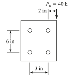
Calculation:
Calculate factored load for LRFD.
Calculate factored load for ASD.
The gross yielding area is calculated as,
The number of bolts required by using LRFD can be calculated as follows.
Where,
We can calculate the
So, we can calculate the bearing strength of the bolt using the formula,
Substitute the all value in the above formula and we get that,
Substitute these values in the design strength formula then we get that,
Now, calculate the number of bolts required for the connection using LRFD by the formula,
Conclusion:
Hence, the resultant force of the bolt is 17.39k.
Want to see more full solutions like this?
Chapter 13 Solutions
Structural Steel Design (6th Edition)


- For the connection shown in the accompanying illustration, Pu = 360 k and Pa = 260 k. Determine by LRFD and ASD the number of 7/8-in A490 bolts required for a bearing-type connection,using A36 steel.Threads are excluded from shear plane.arrow_forwardUsing bearing type connection, determine the number of25mm A490 bolts required, by LRFD only. Determine the design tensilestrength Pu and the allowable tensile strength Pa of the connection ifeight 25mm A325x bearing type bolts are used in each flange. Includeblock shear in your calculations. Use A36 steel for connecting members.arrow_forwardDetermine the effective net area using the U values given on Table 3.2 page77 of the reference book. An MC12x45 is connected through its web with 3 gageslines of 22mm diameter bolts. The gage lines are 76mm on center and the bolts arespaced 80mm on center along the gage line. If the center row of bolt is staggeredwith respect to the outer row, determine the effective net cross-sectional area of thechannel. Assume there are four bolts in each line.Draw the figure first and label it properly. Draw the fracture path using differentcolor or line weights.arrow_forward
- Select a pair of C10 channels for a tension member subjected to a dead load of 120 kips and a live load of275 kips. The channels are placed back to back and connected to a ¾-in gusset plate by 7/8-in Ø bolts.Assume A588 Grade 50 steel for the channels and assume the gusset plate is sufficient. The member is25 ft long. The bolts are arranged in two lines parallel to the length of the member. There are two bolts ineach line 4 in on centerarrow_forwardHow many bolts are required (LRFD and ASD) for the bearing-type connection shown if PD = 120 k and PL = 150 k? A325 7/8 -in bolts, threads excluded from shear planes.arrow_forwardGiven W 16x36 section as shown below (Fy = 50 ksi, Fu = 65ksi). The holes are 3/4 inch in diameter. The connection is bottled at the web only. Assume x= 0.76 inch. 2. The shear lag coefficient U and the effective area Aearrow_forward
- Check the block shear capacity of the connection, use lrfd and asd design expression. Given the lightest W section from Plate 3, connected toa PL% x 10 on its top and bottom flanges, available to support working tensile loads of D = 420 kips and W = 330 kips. The member is to be 20 ft long and is assumed to have two lines of holes for 4-in diameter bolts in each flange. There will be at least three holes in each line 3 inches on center.arrow_forwardDetermine the design strength Puand the allowable strength Pa for the connection shown if 7/8 in A325 bolts (threads excluded) are used in a slip-critical connection with a factor for fillers,hf = 1.0. Assume A36 steel and Class B faying surface and standard size holesarrow_forwardHow many bolts are required for LRFD and ASD for the bearing-type connection shown, if PD = 50 k and PL = 100 k? Fy = 50 ksi, Fu = 70 ksi, 34 -in A325 bolts, threads excluded from shear plane.arrow_forward
- Given W 16x36 section as shown below (Fy = 50ksi, Fu= 65ksi). The holes are 3/4 inch in diameter. The connection is bolted at the web only. Assume x=0.76 inch, determine... 3. The Tensile strength Tn (LRFD) neglecting block shear failure mode.arrow_forwardA bolted connection of the general form shown inFigure 11.6 is to be used to transmit a tension force of 75 kips dead load and100 kips live load by using 7∕8-in. A325 bolts and plates of A992 steel withFy = 50 ksi and Fu = 58 ksi. The outer plates are to be 8 in. wide and thecenter plate is to be 12 in. wide. Find the required thicknesses of the platesand the number of bolts needed if the bolts are placed in two rows. Sketchthe final layout of the connection.arrow_forwardDetermine the LRFD tensile design strength and the ASD tensile strength of the W12 x 30 (Fy = 50 ksi, Fu = 65 ksi) shown in Fig. 3.21 if 7/8 - in bolts are used in the connection. Include block shear calculations for the flanges.arrow_forward

 Structural Analysis (10th Edition)Civil EngineeringISBN:9780134610672Author:Russell C. HibbelerPublisher:PEARSON
 Principles of Foundation Engineering (MindTap Cou...Civil EngineeringISBN:9781337705028Author:Braja M. Das, Nagaratnam SivakuganPublisher:Cengage Learning
 Fundamentals of Structural AnalysisCivil EngineeringISBN:9780073398006Author:Kenneth M. Leet Emeritus, Chia-Ming Uang, Joel LanningPublisher:McGraw-Hill Education
 Traffic and Highway EngineeringCivil EngineeringISBN:9781305156241Author:Garber, Nicholas J.Publisher:Cengage Learning