Concept explainers
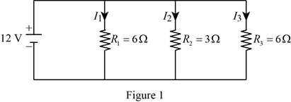
Find the total resistance and the current flow in each branch for the circuit.
Answer to Problem 19P
The total resistance is
The current flows through the branch
The current flows through the branch
The current flows through the branch
Explanation of Solution
Given data:
The supply voltage is
The value of the resistor
The value of the resistor
The value of the resistor
Formula used:
Formula to calculate the total resistance in a parallel circuit,
Here,
Formula to calculate the voltage across the resistor
Here,
Rearrange the equation for the current flow through the resistance
Formula to calculate the voltage across the resistor
Here,
Rearrange the equation for the current flow through the resistance
Formula to calculate the voltage across the resistor
Here,
Rearrange the equation for the current flow through the resistance
Formula to calculate the total current drawn by the circuit,
Calculation:
Refer to Figure problem 12.19 in the textbook, and redraw it as Figure 1, with the two light bulbs represents the resistors
Substitute
Reduce the equation as,
The voltage drop across the each light bulb and the resistor is equal to the
Substitute
Substitute
Substitute
Substitute
Conclusion:
Hence,
The total resistance is
The current flows through the branch
The current flows through the branch
The current flows through the branch
Want to see more full solutions like this?
Chapter 12 Solutions
ENGINEERING FUNDAMENTALS


- Determine the pressure at A in bar gage due to the deflection of the mercury (sp. gr. = 13.6) in the U-tube gage shown in the figure. Round off your answer to to decimal places.arrow_forwardplease do step by step The pipe in figure discharges water from an upper tank to a lower tank as shown. The pipe consists of 500-ft long of a 6-in diameter wrought iron (f = 0.016) Neglect minor losses.arrow_forwardCalculate the change in 5 m long copper wire when its temperature changes by 60∘C. State your assumptions if there are any.arrow_forward
- At a temperature of 60°F, a 0.04-in. gap exists between the ends of the two bars shown in the figure. Bar (1) is an aluminum alloy (E-10,000 ksi; u= 0,32; a= 12.5 x10°/°F] bar with a width of 3 in, and a thickness of 0.75 in. Bar (2) is a stainless steel |E-28,000 ksi; u=0.12; a=9.6x10°/°F] bar with a width of 2 in. and a thickness of 0.75 in. The supports at A and C are rigid. Determine the normal stress in bar (1) at a temperature of 450°Farrow_forwardPlease answer the problem attached image below. And show your solution. Topic:Application in Influence line Draw the influence line first. And next to the problemarrow_forwardRefer to the photo provided and please make sure your handwriting is readable. Both wires have a cross sectional area of 17 mm2 and are constructed of the same material with a modulus of elasticity of 200,000 MPa. 1. Determine the wires' tensile stress at C. 2. Determine the wires' tensile stress at D. 3. Calculate the maximum displacement possible.arrow_forward
- Determine the moment created by the weight of the lamp about point O. The dimensions of the street light post and arm are shown in the accompanying figure. The lamp weighs 95 N.arrow_forwardDetermine the moment created by the weight of the lamp about point O. The dimensions of the street light post and arm are shown in the accompanying figure. The lamp weighs 20 lb.arrow_forwardAn electric baseboard heater has 25 ohms of resistance. The heater uses 9.6amperes of current. Find in volts the voltage required for the heater.arrow_forward
- In series circuits, the current remain same through the circuit while voltage divides in circuit components, why? Justify your answerarrow_forwardPlease show figure and detailed explanation. An open tank in the shape of a frustum of a cone is bound by two hoops, one at the top and the other at the bottom. The diameters at the top and bottom are 2m and 3m, respectively. If the total bursting force is to be taken care of by the hoops, find tension in each hoop if water stands 2 m in the tank. Height of tank is 3.0 m.arrow_forwardA manometer is attached to a closed conduit as shown in figurebelow. Compute the pressure at point A.arrow_forward
 Engineering Fundamentals: An Introduction to Engi...Civil EngineeringISBN:9781305084766Author:Saeed MoaveniPublisher:Cengage Learning
 Residential Construction Academy: House Wiring (M...Civil EngineeringISBN:9781285852225Author:Gregory W FletcherPublisher:Cengage Learning