
Concept explainers
Find the total resistance and the current flow in each branch for the circuit.
Answer to Problem 19P
The total resistance is 1.5 Ω.
The current flows through the branch R1 is 2.0 A.
The current flows through the branch R2 is 4.0 A.
The current flows through the branch R3 is 2.0 A.
Explanation of Solution
Given data:
The supply voltage is 12 V.
The value of the resistor R1 is 6 Ω.
The value of the resistor R2 is 3 Ω.
The value of the resistor R3 is 6 Ω.
Formula used:
Formula to calculate the total resistance in a parallel circuit,
1Rtotal=1R1+1R2+1R3 (1)
Here,
R1, R2, R3 are the resistances.
Formula to calculate the voltage across the resistor R1,
V=I1R1
Here,
I1 is the current flow through the resistance R1.
R1 is the resistance.
Rearrange the equation for the current flow through the resistance R1,
I1=VR1 (2)
Formula to calculate the voltage across the resistor R2,
V=I2R2
Here,
R2 is the resistance.
I2 is the current flow through the resistance R2.
Rearrange the equation for the current flow through the resistance R2,
I2=VR2 (3)
Formula to calculate the voltage across the resistor R3,
V=I3R3
Here,
R3 is the resistance.
I3 is the current flow through the resistance R3.
Rearrange the equation for the current flow through the resistance R3,
I3=VR3 (4)
Formula to calculate the total current drawn by the circuit,
Itotal=I1+I2+I3 (5)
Calculation:
Refer to Figure problem 12.19 in the textbook, and redraw it as Figure 1, with the two light bulbs represents the resistors (R1,R3) are connected in a parallel arrangement with the resistor R2.
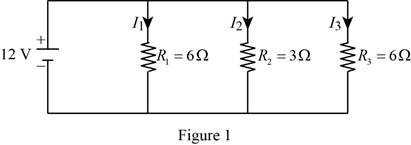
Substitute 6 Ω for R1, 3 Ω for R2 and 6 Ω for R3 in equation (1) to find Rtotal,
1Rtotal=16 Ω+13 Ω+16 Ω=0.662 Ω
Reduce the equation as,
Rtotal=10.662 ΩRtotal=1.5 Ω
The voltage drop across the each light bulb and the resistor is equal to the 12 V.
V=VR1=VR2=VR3=12 V
Substitute 12 V for V and 6 Ω for R1 in equation (2) to find I1,
I1=12 V6 Ω=2 A
Substitute 12 V for V and 3 Ω for R2 in equation (3) to find I2,
I2=12 V3 Ω=4 A
Substitute 12 V for V and 6 Ω for R3 in equation (4) to find I3,
I3=12 V6 Ω=2 A
Substitute 2 A for I1, 4 A for I2 and 2 A for I3 in equation (5) to find Itotal,
Itotal=2 Ω+4 Ω+2 Ω=8 Ω
Conclusion:
Hence,
The total resistance is 1.5 Ω.
The current flows through the branch R1 is 2.0 A.
The current flows through the branch R2 is 4.0 A.
The current flows through the branch R3 is 2.0 A.
Want to see more full solutions like this?
Chapter 12 Solutions
ENGINEERING FUNDAMENTALS


- H.W: An activated sludge process operates under the following data: Q=0.21 m³/s, S.- 250 mg/l, S-6.2 mg/l, MLVSS (X) = 3500 mg/1, 0= 10 days Return sludge concentration (X)= 10000 mg/l, Y=0.5, K₁ =0.06 d', volatile super solid represent 80% of SS, Find: 1- Treatment efficiency 2- Reactor volume 3- Qwa (sludge wasted from areation tank) 4- Qur (sludge wasted from recirculation tank) 5- Quantity of sludge wasted/day 6- Recirculated ratio V.X VX Qwa Qwr= Qwr-Xr 0Xarrow_forwardFor the beam shown, where should a uniformly distributed downward live load, wl, be placed to cause the maximum upward reaction at support A? (D, E, and F are the supports, from left to right, to the right of C.) B C a. From A to B and D to E b. From A to D and E to F c. From B to D and E to F ☑ d. From B to C and D to E L Larrow_forwardQuestion 1 1. A solid shaft of 1.55 m is used as a tractor propeller (prop) shaft. The shaft twists through 1.8 while rotating at 900 rpm. The diameter of the shaft is 60 mm and the modulus of rigidity is 85 GPa. Calculate 1.1 The maximum shear stress in the shaft 1.2 The power transmitted by the shaft. 2. The tractor has undergone minor modifications to increase the transmitted power by 20%. The solid shaft is replaced by a lighter hollow shaft of the same material, with a dimeter ratio of 2:1. Calculate the suitable dimeters of the hollow shaft.arrow_forward
- Use Area Moment Method of Beam Deflectionsarrow_forwardDetermine rotations at all the nodes of the beam and reactions at the supports. Assume support 1 and 3 are roller and support 2 is pinned, L1=1.25m, L2=3.75m and w=60kN/m. Please show all working and FBD's where relevant.arrow_forwardspecific gravity of the soil is 1.41 percentage of water content by weight at field capacity and wilting point are 15% and 7% respectively calculate the equivalent moisture content as equivalent depth for 1.2m root zone: A. At permanent wilting point B. At field capacity C. For ready available water Ex 4-3: If the crop consumptive use in Ex(4-2) is 18 m³/donum/day,calculate: A. Irrigation interval in days B. Field water duty assuming 40% losses during irrigation C. Amount of added water to irrigate one donum. n: CFc- IWC) * As *D Lg dn - Q.te A date. A d9 Q IWC- 20% FC-271 Qg-40e D=100cm sec area of the field. Ed=65% 1 hectare As 1.3arrow_forward
- ۰۹:۲۵ ZV9 HW2-C.pdf Dept: Civil Eng. Kerbala HW2 3rd Year (C) Ex 4-1: The field capacity and wilting point as depth equivalent of soil are 178mm and 102 mm respectively. PAD-60% Calculate the irrigation interval if the water consumptive use is 4.5 mm/day. Ex 4-2: The specific gravity of the soil is 1.41 percentage of water content by weight at field capacity and wilting point are 15% and 7% respectively. a) calculate the equivalent depth of moisture content for 1.2m root zone and PAD 70% at permanent wilting point, at field capacity and for readily available water b) If the crop consumptive use is 18 m/donum/day, calculate: Irrigation interval in days, field water duty assuming 40% losses during irrigation and amount of added water to irrigate one hectare. Ex4-3: Using Blaney-Criddle formula, calculate the irrigation interval through specific interval of plant growth according to the following data: . Mean air temperature 25 C percentage of day light hour through the month 8.4% Crop…arrow_forwardDetermine the global stiffness matrix of the beam shown in Fig. 3. Assume supports at 1 and 3 are rollers and the support at 2 is a pinned support. Indicate the degrees of freedom in all the stiffness matrices. EI is constant, w=60kN/m, L1=1.25m and L2=3.75m please explain how the code numbers for global matrix are determined in detailarrow_forwardFor the truss shown in Fig 2, determine the nodal displacement and member forces for all elements of the truss. Assume for each member A = 0.0015 m2 and E = 200 GPa please show all working, relevant FBD's and use ID's indicated in the diagram, if using an alpha numerical in equations please indicate where it is being applied to in the truss.arrow_forward
- Determine the global stiffness matrix of the beam shown in Fig. 3. Assume supports at 1 and 3 are rollers and the support at 2 is a pinned support. Indicate the degrees of freedom in all the stiffness matrices. EI is constant, w=60kN/m, L1=1.25m and L2=3.45m please explain how the code numbers for global matrix are determined in detailarrow_forward= 20 kips = 20 kips B w₁ = 2 kips/ft 20" 12'- 7760 12" 6"arrow_forward= 20 kips = 20 kips B w₁ = 2 kips/ft 20" 12'- 7760 12" 6"arrow_forward
 Engineering Fundamentals: An Introduction to Engi...Civil EngineeringISBN:9781305084766Author:Saeed MoaveniPublisher:Cengage Learning
 Residential Construction Academy: House Wiring (M...Civil EngineeringISBN:9781285852225Author:Gregory W FletcherPublisher:Cengage Learning
 Residential Construction Academy: House Wiring (M...Civil EngineeringISBN:9781337402415Author:Gregory W FletcherPublisher:Cengage Learning
 Materials Science And Engineering PropertiesCivil EngineeringISBN:9781111988609Author:Charles GilmorePublisher:Cengage Learning
 Solid Waste EngineeringCivil EngineeringISBN:9781305635203Author:Worrell, William A.Publisher:Cengage Learning,