The forces in each member of the truss.
Answer to Problem 12.1P
The forces in each member of the truss are shown below.
The force in member AE is, 2.08 k(Compression).
The force in member BF is, 2.08 k(Tension).
The force in member EF is, 1.67 k(Compression).
The force in member AB is, 1.67 k(Tension).
The force in member CE is, 2.08(Compression).
The force in member BD is, 2.08 k(Tension).
The force in member DE is, 1.67 k(Compression).
The force in member BC is, 1.67 k(Tension).
The force in member AF is, 4.25 k(Compression).
The force in member BE is, 2.5 k(Compression).
The force in member CD is, 5.25 k(Compression).
Explanation of Solution
Check the determinacy of the truss as shown below.
m+r−2j=0
Here, number of members are m, number of reactions are r and number of joints are j.
Substitute 11 for m, 3 for r and 6 for j.
11+3−2×6>02>0
Hence, the given truss is statically indeterminate by 2 degree.
The following diagram shows the free body diagram of the truss.
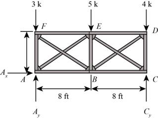
Figure-(1)
Write the equation for moment about A.
ΣMA=0(Cy×16 ft)−(4 k×16 ft)−(5 k×8 ft)=0Cy×16 ft=104 k⋅ftCy=6.5 k
Here, vertical reaction at C is Cy.
Write the equation for sum of vertical forces.
ΣFy=0Ay+Cy−3 k−4 k−5 k=0Ay+Cy=12 k ...... (I)
Here, vertical reaction at A is Ay.
Substitute 6.5 k for Cy in Equation (I).
6.5 k+Ay=12 kAy=(12−6.5)kAy=5.5 k
Consider the force in diagonal members FB is in tension and AE is in compression.
FFB=FAE
Here, force in member AE and FB are FAE and FFB.
Use the method of section and cut the section as shown in figure below and calculate the forces in the members.
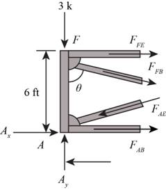
Figure-(2)
Calculate the angles as shown below.
cosθ=35sinθ=45
Here, the angle between the members FA and FB is θ.
Consider the joint F.
Write the Equation for sum of vertical forces.
ΣFy=05.5 k−3 k−FFBcosθ−FAEcosθ=0
Substitute 35 for cosθ.
5.5 k−3 k−2FFB×35=02FFB×35=2.5 kFFB=2.08 k(Tension)FAE=2.08 k(Compression)
Write the equation for the sum of horizontal forces.
ΣFx=0FFE+FFBsinθ=0
Here, force in member FE is FFE.
Substitute 2.08 k for FFB and 45 for sinθ.
FFE+(2.08 k×45)=0FFE=1.67 k(Compression)
Consider joint A.
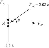
Figure-(3)
Calculate the angles as shown below.
cosθ=45sinθ=35
Write the equation for sum of vertical forces.
ΣFy=0FFA+FAEsinθ−5.5 k=0
Substitute 2.08 k for FAE and 35 for sinθ.
FFA+(2.08 k×35)−5.5 k=0FFA=4.25 k(Compression)
Here, force in member FA is FFA.
Write the Equation for sum of horizontal forces.
ΣFx=0FAB−FAEcosθ=0
Substitute 2.08 k for FAE and 45 for cosθ.
FAB−2.08 k×45=0FAB=1.67 k(Tension)
Here, force in member AB is FAB.
Consider the force in diagonal members BD is in tension and EC is in compression.
FBD=FEC
Here, force in member BD and EC are FBD and FEC.
Use the method of section method and cut the section as shown in figure below and calculate the forces in the members.
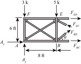
Figure-(4)
Calculate the angles as shown below.
cosθ=45sinθ=35
Write the Equation for sum of vertical forces.
ΣFy=05.5−3−5+FBDsinθ+FECsinθ=02FBDsinθ=2.5
Substitute 35 for sinθ.
2FBD×35=2.5FBD=2.08 k(Tension)FCE=2.08(Compression)
Here, force in the member BD and CE are FBD and FCE.
Write the equation for moment about B.
(FED×6+FECcosθ×6+4×8−6.5×8)k⋅ft=0
Here, force in the member ED is FED.
Substitute 45 for cosθ and 2.08 k for FEC.
(FED×6+2.08×45×6+4×8−6.5×8) k⋅ft=0FED×6 ft=10.01 k⋅ftFED=1.67 k(Compression)
Write the Equation for moment about E.
(FBC×6+FBDcosθ×6−6.5×8+4×8)=0
Here, force in the member BC is FBC.
Substitute 45 for cosθ and 2.08 k for FBD.
(FBC×6+2.08 k×45×6−6.5×8+4×8) k⋅ft=0FBC×6 ft=10.01 k⋅ftFBC=1.67 k(Tension)
Write the Equation for sum of vertical forces.
ΣFy=0FBE+FFBsinθ+FBDsinθ=0
Substitute 35 for sinθ, 2.08 k for FFB and 2.08 k for FBD.
FBE+2.08 k×35+2.08 k×35=0FBE+1.25 k+1.25 k=0FBE=2.5 k(Compression)
Here, force in the member BE is FBE.
Consider the joint C.
Angles will be same as calculated at joint B.
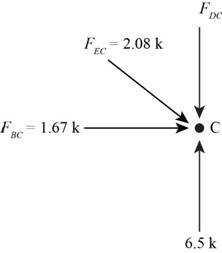
Figure-(5)
Write the Equation for sum of vertical forces.
ΣFy=0FCD+FECsinθ−6.5 k=0
Here, force in the member CD is FCD.
Substitute 35 for sinθ, and 2.08 k for FEC.
FCD+(2.08 k×35)−6.5 k=0FCD=5.25 k(Compression)
Conclusion:
Therefore, the forces in each member of the truss are shown below.
The force in member AE is, 2.08 k(Compression).
The force in member BF is, 2.08 k(Tension).
The force in member EF is, 1.67 k(Compression).
The force in member AB is, 1.67 k(Tension).
The force in member CE is, 2.08(Compression).
The force in member BD is, 2.08 k(Tension).
The force in member DE is, 1.67 k(Compression).
The force in member BC is, 1.67 k(Tension).
The force in member AF is, 4.25 k(Compression).
The force in member BE is, 2.5 k(Compression).
The force in member CD is, 5.25 k(Compression).
Want to see more full solutions like this?
Chapter 12 Solutions
Structural Analysis (10th Edition)

- H.W: show that the equations 1. (x+y)dy+(x-y)dx = 0 2. x²dy+(y²-xy)dx = 0 are homogeneous and solve:arrow_forwardH.W: Solve the differential equation y' - (1+x)(1 + y²) = 0arrow_forwardThe benchmark is 00.00. The backsights are 6.00, 9.32 and 13.75 and 14.00 The foresights are 6.00, 9.00 and 3.22. What is the height of the instrument? H.I. - 100.00 - 124.85 - 43.07- 24.85arrow_forward
- The benchmark is 100.00. The backsights are 4.00, 6.32 and 12.75. The foresights are 6.00, 9.00 and 3.22. What is the elevation of the point? - 95.14 - 123.08 - 104.85 - 81.78arrow_forwardDetermine the stiffness matirx of the entire truss in Global co-ordinate system, clearly indicate the degrees of freedom numbers in the stiffness matrix.arrow_forwardDetermine the stiffness matrices of elements 2, 3 and 4 in the global co-ordinate system. Assume A=0.0015m2 and E=200GPa, indicate the degrees of freedom in all stiffness matricies.arrow_forward
- A short plain concrete column with cross-section dimensions of 12 in x 12 in is to be constructed. If the compressive strength of the concrete (f’c) is 5000 psi, what is the maximum load that can be safely applied to the column? - 600 k - 950 k - 720 k - 347 karrow_forwardThe borrow pit has 2000 cyds of suitable fill. The fill required for the project is 1900 cyds. The swell factor is 10% and the shrinkage factor is 15%. How much more borrow do we need? Or is there extra? - 13 yards extra - 13 yards short - 200 yards extra - 161 yards shortarrow_forwardThe job site has a primary vertical control point with a reference benchmark of 100 ft. An instrument is set up with an HI of 5.42 ft above the BM. A grade stake is set at an elevation of 96 ft. What is the height reading on the rod at the grade stake? - 9.42 ft - 4.00 ft - 1.42 ft - 5.42 ftarrow_forward
- Assume you have a simple beam 16 ft long supported on each end by R1 and R2. There is a concentrated load of 900 lb that is 4 ft from R2. Reaction R1 is pinned 12 ft from the load. Reaction R1 is 225 lb and R2 is 675 lb. What is the maximum bending moment in pounds per foot? - 3,600 - 1,800 - 2,700- 900arrow_forwardA wall form is four-feet high, ten-feet long and ten-feet wide. It is full of fluid concrete. What is the pressure at the bottom of the form? - 86,400 psi - 60,000 psf - 600 psf - 60,000 psiarrow_forwardhe sides of a building are 300 feet long and 200 feet wide. What is the diagonal distance between the opposite corners? - 300 feet - 306 feet - 360.60 feet - 306.6 feetarrow_forward

 Structural Analysis (10th Edition)Civil EngineeringISBN:9780134610672Author:Russell C. HibbelerPublisher:PEARSON
 Principles of Foundation Engineering (MindTap Cou...Civil EngineeringISBN:9781337705028Author:Braja M. Das, Nagaratnam SivakuganPublisher:Cengage Learning
 Fundamentals of Structural AnalysisCivil EngineeringISBN:9780073398006Author:Kenneth M. Leet Emeritus, Chia-Ming Uang, Joel LanningPublisher:McGraw-Hill Education
 Traffic and Highway EngineeringCivil EngineeringISBN:9781305156241Author:Garber, Nicholas J.Publisher:Cengage Learning