
EBK MECHANICS OF MATERIALS
7th Edition
ISBN: 9780100257061
Author: BEER
Publisher: YUZU
expand_more
expand_more
format_list_bulleted
Concept explainers
Videos
Textbook Question
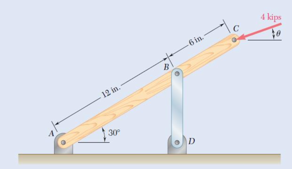
Chapter 1.2, Problem 10P
Link BD consists of a single bar 1 in. wide and
Fig. P1.10
Expert Solution & Answer
Want to see the full answer?
Check out a sample textbook solution
Students have asked these similar questions
THE FRAME SHOWN CONSISTS OF FOUR WOODEN MEMBERS, ABC,
DEF,BE, AND CF.
KNOWING THAT EACH MEMBER HAS A 50X100MM
RECTANGULAR CROSS SECTION AND THAT EACH PIN HAS
A 13 MM DIAMETER, DETERMINE THE MAXIMUM VALUE OF THE
AVERAGE NORMAL STRESS
(A) INMEMBER BE,
(B) IN MEMBER CF.
1.125 mm
750 mm
V2.160 N
100 mm
100 mm
1.000 mm
375 mm
750 mm
12 mm
PROBLEM 1.9
Two horizontal 22 kN
forces are applied to pin B
of the assembly shown.
Knowing that a pin of 20
45 mm
22 kN
mm diameter is used at
each connection, determine
the maximum value of the
22 kN
12 mm
A
60°
average normal stress (a)
in link AB (i.e. at A), and
(b) in link BC (i.e. at
section a-a).
45 mm
45°
a
a
[Ans. (a) 107.3 MPa (b)
-72.96 MPa]
Fig. P1.9
lyp
.29 Two wooden members of uniform rectangular cross section
are joined by the simple glued scarf splice shown. Knowing that
P= 11 kN, determine the normal and shearing stresses in the
glued splice.
150 mm
15
75 mm
Fig. P1.29 and P1.30
Chapter 1 Solutions
EBK MECHANICS OF MATERIALS
Ch. 1.2 - Two solid cylindrical rods AB and BC are welded...Ch. 1.2 - Two solid cylindrical rods AB and BC are welded...Ch. 1.2 - Two solid cylindrical rods AB and BC are welded...Ch. 1.2 - Two solid cylindrical rods AB and BC are welded...Ch. 1.2 - A strain gage located at C on the surface of bone...Ch. 1.2 - Two brass rods AB and BC, each of uniform...Ch. 1.2 - Each of the four vertical links has an 8 36-mm...Ch. 1.2 - Link AC has a uniform rectangular cross section 18...Ch. 1.2 - Three forces, each of magnitude P = 4 kN, are...Ch. 1.2 - Link BD consists of a single bar 1 in. wide and 12...
Ch. 1.2 - For the Pratt bridge truss and loading shown,...Ch. 1.2 - The frame shown consists of four wooden members,...Ch. 1.2 - An aircraft tow bar is positioned by means of a...Ch. 1.2 - Two hydraulic cylinders are used to control the...Ch. 1.2 - Determine the diameter of the largest circular...Ch. 1.2 - Two wooden planks, each 12 in. thick and 9 in....Ch. 1.2 - When the force P reached 1600 lb, the wooden...Ch. 1.2 - A load P is applied to a steel rod supported as...Ch. 1.2 - The axial force in the column supporting the...Ch. 1.2 - Three wooden planks are fastened together by a...Ch. 1.2 - A 40-kN axial load is applied to a short wooden...Ch. 1.2 - An axial load P is supported by a short W8 40...Ch. 1.2 - Link AB, of width b = 2 in. and thickness t=14...Ch. 1.2 - Determine the largest load P that can be applied...Ch. 1.2 - Knowing that = 40 and P = 9 kN, determine (a) the...Ch. 1.2 - The hydraulic cylinder CF, which partially...Ch. 1.2 - For the assembly and loading of Prob. 1.7,...Ch. 1.2 - Two identical linkage-and-hydraulic-cylinder...Ch. 1.5 - Two wooden members of uniform rectangular cross...Ch. 1.5 - Two wooden members of uniform rectangular cross...Ch. 1.5 - The 1.4-kip load P is supported by two wooden...Ch. 1.5 - Two wooden members of uniform cross section are...Ch. 1.5 - A centric load P is applied to the granite block...Ch. 1.5 - A 240-kip load P is applied to the granite block...Ch. 1.5 - A steel pipe of 400-mm outer diameter is...Ch. 1.5 - A steel pipe of 400-mm outer diameter is...Ch. 1.5 - A steel loop ABCD of length 5 ft and of 38-in....Ch. 1.5 - Link BC is 6 mm thick, has a width w = 25 mm, and...Ch. 1.5 - Link BC is 6 mm thick and is made of a steel with...Ch. 1.5 - Members AB and BC of the truss shown are made of...Ch. 1.5 - Members AB and BC of the truss shown are made of...Ch. 1.5 - Link AB is to be made of a steel for which the...Ch. 1.5 - Two wooden members are joined by plywood splice...Ch. 1.5 - For the joint and loading of Prob. 1.43, determine...Ch. 1.5 - Three 34-in.-diameter steel bolts are to be used...Ch. 1.5 - Three steel bolts are to be used to attach the...Ch. 1.5 - A load P is supported as shown by a steel pin that...Ch. 1.5 - A load P is supported as shown by a steel pin that...Ch. 1.5 - A steel plate 14 in. thick is embedded in a...Ch. 1.5 - Determine the factor of safety for the cable...Ch. 1.5 - Link AC is made of a steel with a 65-ksi ultimate...Ch. 1.5 - Solve Prob. 1.51, assuming that the structure has...Ch. 1.5 - Each of the two vertical links CF connecting the...Ch. 1.5 - Solve Prob. 1.53, assuming that the pins at C and...Ch. 1.5 - In the structure shown, an 8-mm-diameter pin is...Ch. 1.5 - In an alternative design for the structure of...Ch. 1.5 - Prob. 57PCh. 1.5 - The Load and Resistance Factor Design method is to...Ch. 1 - In the marine crane shown, link CD is known to...Ch. 1 - Two horizontal 5-kip forces are applied to pin B...Ch. 1 - For the assembly and loading of Prob. 1.60,...Ch. 1 - Two steel plates are to be held together by means...Ch. 1 - A couple M of magnitude 1500 N m is applied to...Ch. 1 - Knowing that link DE is 18 in. thick and 1 in....Ch. 1 - A 58-in.-diameter steel rod AB is fitted to a...Ch. 1 - In the steel structure shown, a 6-mm-diameter pin...Ch. 1 - Prob. 67RPCh. 1 - A force P is applied as shown to a steel...Ch. 1 - The two portions of member AB are glued together...Ch. 1 - The two portions of member AB are glued together...
Additional Engineering Textbook Solutions
Find more solutions based on key concepts
Describe the structural changes that take place when a plain-carbon eutectoid steel is slowly cooled from the a...
Foundations of Materials Science and Engineering
Three rigid bodies, 2,3, and 4, are connected by four springs as shown in the figure. A horizontal force of 1,0...
Introduction To Finite Element Analysis And Design
17–1C A high-speed aircraft is cruising in still air. How does the temperature of air at the nose of the aircra...
Thermodynamics: An Engineering Approach
The triple jump is a track-and-field event in which an athlete gets a running start and tries to leap as far as...
Vector Mechanics For Engineers
Repeat Problem 4-6 except solve by the vector loop method.
DESIGN OF MACHINERY
List several uses of the arbor press.
Machine Tool Practices (10th Edition)
Knowledge Booster


Learn more about
Need a deep-dive on the concept behind this application? Look no further. Learn more about this topic, mechanical-engineering and related others by exploring similar questions and additional content below.Similar questions
- ! 4 Required information Two horizontal 5.5-kip forces (P) are applied to pin B of the assembly shown. A 0.8-in. diameter pin is used at each connection. Part 2 of 2 0.5 in. 1.8 in. P 0.5 in. 60° 1.8 in. Determine the maximum value of the normal average stress at the midpoint of link BC. The maximum value of the normal average stress at the midpoint of link BC is ksi.arrow_forwardLink BD consists of a single wooden member 38 mm wide and 19.2 mm thick. Knowing that each pin has a 14.3-mm diameter, determine the maximum value of the average normal stress (in MPa) in link BD if θ= 0° and P = 26.7. Round off the final answer to three decimal places.arrow_forward5. The load P applied to a steel rod is distributed to a timber support by an annular washer. The diameter of the rod is 22 mm and the inner diameter of the washer is 25 mm, which is slightly larger than the diameter of the hole. Determine the smallest allowable outer diameter d of the washer, knowing that the axial normal stress in the steel rod is 35 MPa and the average bearing stress between the washer and the timber must not exceed 5 MPa. - 22 mmarrow_forward
- 6. Link BD consists of a single bar 30 mm wide and 12 mm thick. Knowing that each pin has a 10 mm diameter, determine the maximum value of the average normal stress in link BD if (a) 0 = 0°, (b) 0 = 90°. 150 m 00 mm 5B Page 2 of 3arrow_forward1.14 Two hydraulic cylinders are used to control the position of the robotic arm ABC. Knowing that the control rods attached at A and D each have a 20-mm diameter and happen to be parallel in the position shown, determine the average normal stress in (a) member AE, (b) member DG. 400 mm E - 300 mm- A Fig. P1.14 F G 150 mm 150 mm 200 mm B D 600 mm- 800 N Carrow_forwardPROBLEM 1.3 3 in. 30 kips Two solid cylindrical rods AB and BC are welded together at B and loaded as shown. Determine the magnitude of the force P for which the tensile stress in rod AB is twice the magnitude of the compressive stress in rod BC. 30 kips 40 in PROBLEM 1.4 In Prob. 1.3, knowing that P = 40 kips, determine the average normal stress at the midsection of (a) rod AB, (b) rod BC.arrow_forward
- Link BD consists of a single bar 30 mm wide and 12 mm thick. Knowing that each pin has a 10-mm diameter, determine the maximum value of the average normal stress in link BD if (a) θ =0°(b) θ =90°.arrow_forwardKnowing that the allowable stress in section ABD is 80 MPa, determine the largest force P that can be applied to the bracket shown. 18 mmX 12 mm 40 mm 12 mmarrow_forwardLink BD consists of a single wooden member 38.2 mm wide and 20.4 mm thick. Knowing that each pin has a 13.3-mm diameter, determine the maximum value of the average normal stress (in MPa) in link BD if θ= 0° and P = 30.4. Round off the final aswer to three decimal places.arrow_forward
- +3 in- B in. A vertical force P of magnitude 20 kips is applied at point C located on the axis of symmetry of the cross section of a short column. Knowing that y = 5 in., determine (a) the stress at point A, (b) the stress at point B, (c) the location of the neutral axis. 2 in. 4 in. A 2 in. 2 in. 1 in. (a) (b)arrow_forwardTwo horizontal 4.3-kip forces are applied to pin Bof the assembly shown. Knowing that a pin of 1.05-in. diameter is used at each connection, determine the bearing stress (in psi) at B in member AB. 0.5 in. B 1.8 in. P 0.5 in. 60° 1.8 in. 45° Carrow_forwardThe four forces shown are applied to a rigid plate supported by a solid steel post of radius a. Knowing that P= 24 kips and a= 1.6 in., determine the maximum stress in the post when (a) the force at D is removed, (b) the forces at C and D are removedarrow_forward
arrow_back_ios
SEE MORE QUESTIONS
arrow_forward_ios
Recommended textbooks for you
 Elements Of ElectromagneticsMechanical EngineeringISBN:9780190698614Author:Sadiku, Matthew N. O.Publisher:Oxford University Press
 Mechanics of Materials (10th Edition)Mechanical EngineeringISBN:9780134319650Author:Russell C. HibbelerPublisher:PEARSON
 Thermodynamics: An Engineering ApproachMechanical EngineeringISBN:9781259822674Author:Yunus A. Cengel Dr., Michael A. BolesPublisher:McGraw-Hill Education
 Control Systems EngineeringMechanical EngineeringISBN:9781118170519Author:Norman S. NisePublisher:WILEY
 Mechanics of Materials (MindTap Course List)Mechanical EngineeringISBN:9781337093347Author:Barry J. Goodno, James M. GerePublisher:Cengage Learning
 Engineering Mechanics: StaticsMechanical EngineeringISBN:9781118807330Author:James L. Meriam, L. G. Kraige, J. N. BoltonPublisher:WILEY
Elements Of Electromagnetics
Mechanical Engineering
ISBN:9780190698614
Author:Sadiku, Matthew N. O.
Publisher:Oxford University Press
Mechanics of Materials (10th Edition)
Mechanical Engineering
ISBN:9780134319650
Author:Russell C. Hibbeler
Publisher:PEARSON
Thermodynamics: An Engineering Approach
Mechanical Engineering
ISBN:9781259822674
Author:Yunus A. Cengel Dr., Michael A. Boles
Publisher:McGraw-Hill Education
Control Systems Engineering
Mechanical Engineering
ISBN:9781118170519
Author:Norman S. Nise
Publisher:WILEY
Mechanics of Materials (MindTap Course List)
Mechanical Engineering
ISBN:9781337093347
Author:Barry J. Goodno, James M. Gere
Publisher:Cengage Learning
Engineering Mechanics: Statics
Mechanical Engineering
ISBN:9781118807330
Author:James L. Meriam, L. G. Kraige, J. N. Bolton
Publisher:WILEY
EVERYTHING on Axial Loading Normal Stress in 10 MINUTES - Mechanics of Materials; Author: Less Boring Lectures;https://www.youtube.com/watch?v=jQ-fNqZWrNg;License: Standard YouTube License, CC-BY