
Videos
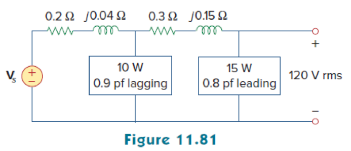
For the circuit in Fig. 11.81, find Vs.
Find the voltage
Answer to Problem 62P
The voltage
Explanation of Solution
Given data:
Refer to Figure 11.81 in the textbook.
The voltage
For load A,
The real power
The power factor
For load B,
The real power
The power factor
Formula used:
Write the expression to find the complex power.
Here,
Write the expression to find the power factor
Here,
Write the expression to find the real power.
Write the expression to find the reactive power.
Write the expression to find the output voltage.
Calculation:
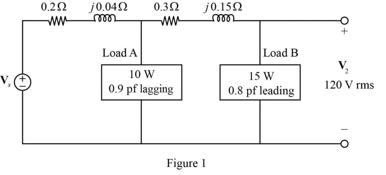
The given Figure 11.81 is redrawn as shown in Figure 1.
For load A:
Substitute
Substitute
Rearrange the equation as follows,
Substitute
Substitute
For load B:
Substitute
Substitute
Rearrange the equation as follows,
Substitute
Substitute
As the power factor is leading, the load is capacitive. Therefore, the equation becomes,
The modified Figure is shown in Figure 2.
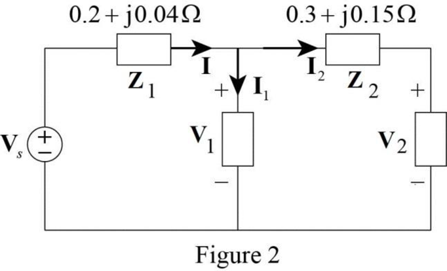
Substitute
The voltage
Substitute
Substitute
Convert the equation from polar to rectangular form.
The current
Substitute
The voltage supplied by the source is,
Substitute
Convert the equation from rectangular to polar form.
Conclusion:
Thus, the voltage
Want to see more full solutions like this?
Chapter 11 Solutions
EE 98: Fundamentals of Electrical Circuits - With Connect Access


- A factory take 500kW at 0.75 pf lagging from a constant voltage AC supply. A synchronous condenser with negligible losses is connected to the factory to improve the power factor to 0.95 lagging. find the kVAR of the synchronous condenser.arrow_forwardWhen the waveform shown in fig. (1) is applied to true responding ac voltmeter, the output would be (5.314 V). If the same signal is applied to average responding ac voltmeter, what will be: 1. The indicate value. 2. The true value. 3. The true form factor. 4. The indicate crest factor.arrow_forwardAs a electrical engineering student what is the problem in power Quality: Ensuring that the voltage and frequency of the power supplied to customers is of good quality and within the acceptable limits.arrow_forward
- 2.1 An ESKOM engineer made the following recommendation for 220 V, 50Hz line. 150µF capacitor and a 75 mH inductor for the TCR to correct the power factor to be at unity. What is the delay angle when the load current has a reactive component of -j9 A?arrow_forward11 Consider the following circuit used to provide power for an inductive RL load. The input voltage is Vs=150V and the load has a 30 impedance value. The thyristor is working at a frequency fs = 2 kHz. The discharge current is to be limited to 50A and the required dv/dt is 50V/us. If the value of Cs is equal to 0.158µF, then the snubber losses are equal to: put of question T: T R Vs Select one: O a. 4.56W O b. 2.56W Oc. 5.45W Od. 3.56Warrow_forwardDetermine the output voltage for the circuit of Fig. 11.52arrow_forward
- Digital multimeters in an AC mode measure average values of voltage and current. Select one: True Falsearrow_forwardFor the circuit in Fig. 11.79, find Vo, and the input power factor.arrow_forwardA 75MW power plant has an average load of 35000kW and a load factor of 65%. Find the reserved carried over and above peak loadarrow_forward
- Three loads connect in parallel to a 220 v, 50 Hz supply, each drawing its current thus: (5 £-60, 8 £ -30, 10 £ -20). Find the value of capacitor to be connecting across the supply to increase the total power factor to 0.92 lagging.arrow_forward11. Two coupled coils have self-inductances L1 = 2 Hand L2 = 0.5 H, and a coefficient of coupling K = 0.9. Determine the turns ratio N1/N2 of the two coils. ww w а. 2 b. 0.2 c. 0.5 d. 0.9arrow_forwardA coil has an inductance of 39.8 microH and a series resistance of 20 ohms. Find its impedance at a frequency of 100 kHz and the current through the circuit if the voltage drop across the circuit is 80 V. Also find the voltage drop across the resistor u the voltage drop across the coil .arrow_forward
 Introductory Circuit Analysis (13th Edition)Electrical EngineeringISBN:9780133923605Author:Robert L. BoylestadPublisher:PEARSON
 Delmar's Standard Textbook Of ElectricityElectrical EngineeringISBN:9781337900348Author:Stephen L. HermanPublisher:Cengage Learning
 Programmable Logic ControllersElectrical EngineeringISBN:9780073373843Author:Frank D. PetruzellaPublisher:McGraw-Hill Education
 Fundamentals of Electric CircuitsElectrical EngineeringISBN:9780078028229Author:Charles K Alexander, Matthew SadikuPublisher:McGraw-Hill Education
 Electric Circuits. (11th Edition)Electrical EngineeringISBN:9780134746968Author:James W. Nilsson, Susan RiedelPublisher:PEARSON
 Engineering ElectromagneticsElectrical EngineeringISBN:9780078028151Author:Hayt, William H. (william Hart), Jr, BUCK, John A.Publisher:Mcgraw-hill Education,