
Videos
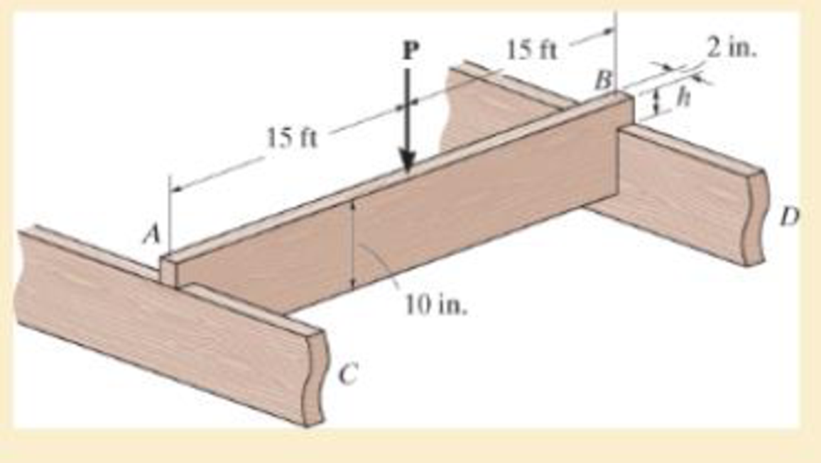
The simply supported joist is used in the construction of a floor for a building. In order to keep the floor low with respect to the sill beams C and D, the ends of the joist are notched as shown. If the allowable shear stress is τallow = 350 psi and the allowable bending stress is σallow = 1700 psi, determine the smallest height h so that the beam will support a load of P = 600 lb. Also, will the entire joist safely support the load? Neglect the stress concentration at the notch.
Want to see the full answer?
Check out a sample textbook solution
Chapter 11 Solutions
Mechanics of Materials
Additional Engineering Textbook Solutions
Engineering Mechanics: Dynamics (14th Edition)
Automotive Technology: Principles, Diagnosis, And Service (6th Edition) (halderman Automotive Series)
EBK FUNDAMENTALS OF THERMODYNAMICS, ENH
Thinking Like an Engineer: An Active Learning Approach (3rd Edition)
Fluid Mechanics: Fundamentals and Applications
Fluid Mechanics Fundamentals And Applications


- The singular force F will be applied to the beam with a hollow rectangular cross section. Accordingly, the location and value of the maximum normal stress that will occur in the whole beam is given correctly in the following? F =400 N, L1 = 3m, L2 = 2m, h1=48mm, h2 =72mm, b1=10mm, b2=20mmarrow_forwardThe axle of the freight train is subjected to loadings as shown below. The diameter of the axle is 137.5 mm. If it is supported by two journal bearings at C and D, determine the maximum bending stress. Include a FBD, SFD and BMD using either the section or graphical method. Draw a cross-section of the shaft and indicate the points of maximum tension and compression. A B 250 mm 100 kN 1500 mm- Answer 0= +98 MPa 250 mm 100 kNarrow_forwardQuestion 1: A member having the dimensions shown is used to resist an internal bending moment of M kNm. Determine the maximum stress in the member if the moment is applied (a) about the z axis (as shown) (b) about the y axis. Sketch the stress distribution for each case. Take: M= 98 kNm mm A= 208 mm B= 158 mm B mm Solution: The moment of inertia of the cross-section about z and y axes are 1 AB³ 12 |(10-) m* 1 ВАЗ — 12 I, |(10) m* = For the bending about z axis, c = m Mc O pax MPа Iz For the bending about y axis, c = m Mc MPа Iy max z MPa KN=M Omax Y MPa. M KN-M MPa O max Z Omax Y MPaarrow_forward
- If the simply supported beam is subjected to the load shown below, determine the following: c- c - The internal bending moment acting on the cross-section through point C. d- d- The shear stress at section C.arrow_forwardDetermine the shear stress (in Mpa) in the 28.54-mm-diameter pin at B that support the beam if P = 35.79 kN, a = 2.76 m, and b = 5.95 m.arrow_forwardA strip of steel 3 mm thick and 35 mm wide is bent round a cylindrical drum 4 mm in diameter. Determine the maximum stress set up in the strip and the bending moment which has to be applied to bend the strip to this curvature (E = 200 GPa) A hollow short cast iron column has outside and inside diameters of 250 mm and 150 mm respectively. The column is subjected to an axial load applied at a distance of 60 mm from the center of the section. (a) Calculate the maximum safe load if the allowable stresses are 110 MPa compressive and 30 MPa tensile, calculate also the position of the NA.arrow_forward
- In a 2.5 cantilevered I-beam, 2500 kg weight is applied at 0.75 meter from the free end. If the allowable stress in beam is 120 Mpa, determine the section modulus and The base and height of the beam if the base is 75% of its height mm.arrow_forwardA member having the dimensions shown is used to resist an internal bending moment of M kNm. Determine the maximum stress in the member if the moment is applied (a) about the z axis (as shown) (b) about the y axis. Sketch the stress distribution for each case. Take: M= 90 kNm A mm A= 200 mm B= 150 mm B mm Solution: The moment of inertia of the cross-section about z and y axes are I;-4 1 - AB³ 12 (10) m* I BA = (10) m*arrow_forwardDetermine the shear stress (in Mpa) in the 23.5-mm-diameter pin at A that support the beam if P = 28.36 kN, a = 2.25 m, and b = 6.56 m.arrow_forward
- Find the second moment of area, the location of the neutral axis, and the distances from the neutral axis to the top and bottom surfaces. Consider that the section is transmitting a positive bending moment about the z axis, Mz, where M₂ = 10 kip-in if the dimensions of the section are given in ips units, or M₂ = 1.13 kN·m if the dimensions are in Sl units. Determine the resulting stresses at the top and bottom surfaces and at every abrupt change in the cross section. From the figure Z 1 in 112 in y in → ← ¹ in 12 in D C B A ++ in The area is determined to be 2.0625 in². The distances from the neutral axis to the top and bottom surfaces are determined to be 0.858 x in and The second moment of area is determined to be 0.447 in 4. 1.017 xin.arrow_forwardFind the second moment of area, the location of the neutral axis, and the distances from the neutral axis to the top and bottom surfaces. Consider that the section is transmitting a positive bending moment about the z axis, Mz, where M₂ = 10 kip-in if the dimensions of the section are given in ips units, or M₂ = 1.13 kN·m if the dimensions are in Sl units. Determine the resulting stresses at the top and bottom surfaces and at every abrupt change in the cross section. From the figure, с - 12.5 B A y I 50 100 75 12.5- 12.5 25 D 100 The area is determined to be 3750 mm² The distances from the neutral axis to the top and bottom surfaces are determined to be 57.292 The second moment of area is determined to be 4.293 x 106 mm4. mm and 42.708 ✪ mm.arrow_forwardThe axle of the freight train is subjected to loadings as shown below. The diameter of the axle is 137.5 mm. If it is supported by two journal bearings at C and D, determine the maximum bending Stress. Include a FBD, SFD and BMD using either the section or graphical method. Draw a cross-section of the shaft and indicate the points of maximum tension and compression.arrow_forward
 Elements Of ElectromagneticsMechanical EngineeringISBN:9780190698614Author:Sadiku, Matthew N. O.Publisher:Oxford University Press
 Mechanics of Materials (10th Edition)Mechanical EngineeringISBN:9780134319650Author:Russell C. HibbelerPublisher:PEARSON
 Thermodynamics: An Engineering ApproachMechanical EngineeringISBN:9781259822674Author:Yunus A. Cengel Dr., Michael A. BolesPublisher:McGraw-Hill Education
 Control Systems EngineeringMechanical EngineeringISBN:9781118170519Author:Norman S. NisePublisher:WILEY
 Mechanics of Materials (MindTap Course List)Mechanical EngineeringISBN:9781337093347Author:Barry J. Goodno, James M. GerePublisher:Cengage Learning
 Engineering Mechanics: StaticsMechanical EngineeringISBN:9781118807330Author:James L. Meriam, L. G. Kraige, J. N. BoltonPublisher:WILEY