
Videos
Consider a combined gas–steam power plant that has a net power output of 280 MW. The pressure ratio of the gas-turbine cycle is 11. Air enters the compressor at 300 K and the turbine at 1100 K. The combustion gases leaving the gas turbine are used to heat the steam at 5 MPa to 350°C in a heat exchanger. The combustion gases leave the heat exchanger at 420 K. An open feedwater heater incorporated with the steam cycle operates at a pressure of 0.8 MPa. The condenser pressure is 10 kPa. Assuming isentropic efficiencies of 100 percent for the pump, 82 percent for the compressor, and 86 percent for the gas and steam turbines, determine (a) the mass flow rate ratio of air to steam, (b) the required rate of heat input in the combustion chamber, and (c) the thermal efficiency of the combined cycle.
(a)
The mass flow rate ratio of the air to the steam.
Answer to Problem 86P
The mass flow rate ratio of the air to the steam is
Explanation of Solution
Show the
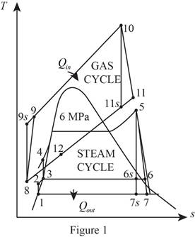
Refer Figure 1.
Consider the gas cycle (topping cycle) and their respective process states such as 8, 9,
At state 8:
The air enters the compressor at the temperature of
Refer Table A-17, “Ideal-gas properties of air”.
The enthalpy
Write the relative pressure and absolute pressure relation for the process 8-9-
Here, the relative pressure is
Write the formula for isentropic efficiency of compressor for the process 8-9-
Here, the enthalpy is
At state 10:
The air enters the turbine at the temperature of
Refer Table A-17, “Ideal-gas properties of air”.
The enthalpy
Write the relative pressure and absolute pressure relation for the process 10-11-
Write the formula for isentropic efficiency of gas turbine
At state 12: (heat exchanger)
The enthalpy
Refer Figure 1.
Consider the steam cycle (bottoming cycle) and their respective process states such as 1, 2, 3, 4, 5, 6,
At state 1: (Pump I inlet)
The water exits the condenser as a saturated liquid at the pressure of
Refer Table A-5, “Saturated water-Pressure table”.
The enthalpy
At state 2:
Write the formula for work done by the pump during process 1-2.
Here, the specific volume is
Write the formula for enthalpy
At state 3: (Pump II inlet)
The water exits the open feed water heater as a saturated liquid at the pressure of
Refer Table A-5, “Saturated water-Pressure table”.
The enthalpy
At state 4:
Write the formula for work done by the pump during process 3-4.
Here, the specific volume is
Write the formula for enthalpy
At state 5:
The steam enters the turbine as superheated vapour.
Refer Table A-6, “Superheated water”.
The enthalpy
At state
The steam expanded to the pressure of
The quality of water at state
The enthalpy at state
Here, the enthalpy is
Refer Table A-5, “Saturated water-Pressure table”.
Obtain the following properties corresponding to the pressure of
The isentropic efficiency of the steam turbine for the process 5-6-
At state
The steam enters the condenser at the pressure of
The quality of water at state
The enthalpy at state
Here, the subscript
Refer Table A-5, “Saturated water-Pressure table”.
Obtain the following properties corresponding to the pressure of
The isentropic efficiency of the steam turbine for the process 5-7-
Here, the subscript
Write the general energy rate balance equation.
Here, the rate of energy in is
Consider the heat exchanger operates on steady state. Hence, the rate of change in net energy of the system is zero.
The Equation (XVI) is reduced as follows for the heat exchanger.
Here, the mass flow rate of air is
Conclusion:
Substitute
Refer Table A-17, “Ideal-gas properties of air”.
The enthalpy
Substitute
Substitute
Refer Table A-17, “Ideal-gas properties of air”.
The enthalpy
Substitute
Substitute
Substitute
Substitute
Equation (VII).
Substitute
From Figure 1.
Substitute
Substitute
Equation (X).
Substitute
Substitute
Substitute
Equation (XIII).
Substitute
Substitute
Thus, the mass flow rate ratio of the air to the steam is
(b)
The required rate of heat input in the combustion chamber.
Answer to Problem 86P
The required rate of heat input in the combustion chamber is
Explanation of Solution
Refer Equation (XV).
Consider the open feed water heater operates on steady state. Hence, the rate of change in net energy of the system is zero.
Write the energy rate balance equation for open feed water heater.
Rewrite the Equation (XVII) in terms of mass fraction
Here, the mass fraction steam extracted from the turbine to the inlet mass of the boiler
Write the formula for work output of the steam turbine.
Write the formula for net work output of the steam cycle.
Write the formula for net work output of the gas cycle.
Write the formula for the net work output of the gas-steam cycle per unit mass of gas.
Write the formula for mass flow rate of air through the compressor.
Write the formula for rate of heat input to the combustion chamber.
Conclusion:
Substitute
Equation (XVIII).
Substitute
Substitute
Substitute
Substitute
Substitute
Substitute
Equation (XXIV).
Thus, the required rate of heat input in the combustion chamber is
(c)
The thermal efficiency of the combined cycle.
Answer to Problem 86P
The thermal efficiency of the combined cycle is
Explanation of Solution
Write the formula for thermal efficiency.
Conclusion:
Substitute
Thus, the thermal efficiency of the combined cycle is
Want to see more full solutions like this?
Chapter 10 Solutions
THERMODYNAMICS LLF W/ CONNECT ACCESS


- QII/ The gas-turbine portion of a combined gas—steam power plant has a pressure ratio of 16. Air enters the compressor at 300 K at a rate of 14 kg/s and is heated to 1500 K in the combustion chamber. The combustion gases leaving the gas turbine are used to heat the steam to 400 0 C at 10 MPa in a heat exchanger. The combustion gases leave the heat exchanger at 420 K. The steam leaving the turbine is condensed at 15 kPa. Assuming all the compression and expansion processes to be isentropic, determine (a) the mass flow rate of the steam, (b) the net power output, and (c) the thermal efficiency of the combined cycle. For air, assume constant specific heats at room temperature. Answers:(a) 1.275 kg/s, (b) 7819 kW, (c) 66.4 percent.arrow_forwardRequired information NOTE: This is a multi-part question. Once an answer is submitted, you will be unable to return to this part. Consider a combined gas-steam power plant that has a net power output of 270 MW. The pressure ratio of the gas turbine cycle is 11. Air enters the compressor at 300 K and the turbine at 1100 K. The combustion gases leaving the gas turbine are used to heat the steam at 5 MPa to 350°C in a heat exchanger. The combustion gases leave the heat exchanger at 420 K. An open feedwater heater incorporated with the steam cycle operates at a pressure of 0.8 MPa. The condenser pressure is 10 kPa. Assume isentropic efficiencies of 100 percent for the pump, 82 percent for the compressor, and 86 percent for the gas and steam turbines. Determine the required rate of heat input in the combustion chamber. (You must provide an answer before moving on to the next part.) The required rate of heat input in the combustion chamber is kW.arrow_forwardQ12//Consider a combined gas-steam power plant that has a net power output of 450 MW. The pressure ratio of the gas-turbine cycle is 14. Air enters the compressor at 300 K and the turbine at 1400 K. The combustion gases leaving the gas turbine are used to heat the steam at 8 MPa to 400°C in a heat exchanger. The combustion gases leave the heat exchanger at 460 K. An open feedwater heater incorporated with the steam cycle operates at a pressure of 0.6 MPa. The condenser pressure is 20 kPa. Assuming all the compression and expansion processes to be isentropic, determine (a) the mass flow rate ratio of air to steam, (b) the required rate of heat input in the combustion chamber, and (c) the thermal efficiency of the combined cycle.arrow_forward
- 7. The gas-turbine cycle of a combined gas-steam power plant has a pressure ratio of 12. Air enters the compressor at 310 K and the turbine at 1400 K. The combustion gases leaving the gas turbine are used to heat the steam at 12.5 MPa to 500 °C in a heat exchanger. The combustion gases leave the heat exchanger at 247 °C. Steam expands in a high-pressure turbine to a pressure of 2.5 MPa and is reheated in the combustion chamber to 550 °C before it expands in a low-pressure turbine to 10 kPa. The mass flow rate of steam is 12 kg/s. Assuming all the compression and expansion processes to be isentropic, determine 154 kJ/ 1.44 10° kJ/s 59.1% (a) the mass flow rate of air in the gas-turbine cycle, (b) the rate of total heat input, and (c) the thermal efficiency of the combined cycle.arrow_forwardA steam power plant operating on the intermediate steam Rankine cycle produces a net power of 160 MW. Water vapor enters the turbine at a pressure of 15 MPa and a temperature of 600 oC, and the condenser at a pressure of 15 kPa. The isentropic efficiency of the turbine is 85 percent and the isentropic efficiency of the pumps is 90 percent. In order to heat the feed water, some steam is separated from the turbine at a pressure of 0.6 MPa and sent to the open feedwater heater and exits the heater as a saturated liquid. Accordingly, fill in the blanks below. (Pump 1 inlet will be considered as saturated liquid.) a) The mass flow rate of the steam passing through the boiler is m5= ..... kg/s. b) The mass flow rate of the steam separated from the turbine to heat the feed water is m6= ...... kg/s. c) The heat entering the cycle is Qin = ...... kW. d) The heat released from the cycle is Qout = ...... kW. e) The power produced in the turbine is WTurbine= ...... kW. f) The power consumed in…arrow_forwardConsider a steam power plant that operates on a simple ideal Rankine cycle and has a net power output of 45MW. Steam enters the turbine at 7 MPa and 500 ˚C and is cooled in the condenser at a pressure of 10kPa by running cooling water from a lake through the tubes of the condenser at a rate of 2000 kg/s. Show the schematic diagram of the power plant and draw the cycle on a T-s diagram with respect to saturation lines. Also, determine (a) the thermal efficiency of the cycle, (b) the mass flow rate of the steam, and (c) the rise in temperature of the cooling water. Repeat your calculations assuming an isentropic efficiency of 85 and 90 for the turbine and the pump, respectively.arrow_forward
- If the thermal efficiency of a steam power plant operating on the simple ideal rankine cycle is 26% and the steam is condensed in the condenser at a pressure of 75 kpa and Enthalpy of the steam which leave the turbine is 3166 kj/kg. determine the steam conditions (pressure and temperature ) which enters the turbine of the power plant.arrow_forwardA simple Rankine cycle uses water as the working fluid. The boiler operates at 6000 kPa and the condenser at 50 kPa. At the entrance to the turbine, the temperature is 450°C. The isentropic efficiency of the turbine is 94 percent, pressure and pump losses are negligible, and the water leaving the condenser is subcooled by 6.3°C. The boiler is sized for a mass flow rate of 19 kg/s. Determine the rate at which heat is added in the boiler, the power required to operate the pumps, the net power produced by the cycle, and the thermal efficiency. Use steam tables. The rate at which heat is added in the boiler is 4192.12 kW. The power required to operate the pumps is 59354.47 kW. The net power produced by the cycle is -55162.35 ✪ kW. The thermal efficiency of the cycle is 13.16 %.arrow_forwardA steam power plant operates on a Rankine cycle and has a net power output of 50 MW. Steam enters the turbine at 1000 psia and 1000 F and is cooled in the condenser at a pressure of 2 psia. The enthalpy at the exit of the pump is 97.588 Btu/lbm. The mass flow rate of the steam is 104.09 Ibm/s. In the question that follows, select the answer that is closest to the true value. What is the heat going to the boiler in units of Btu/s ?arrow_forward
- A Combined power plant consists of a gas turbine unit and a steam turbine unit. The exhaust gas from the open-cycle gas turbine is the supply gas to the steam generator of the steam turbine cycle at which additional fuel is burned in the gas. The pressure ratio for the gas turbine is 30 the air inlet temperature is 180C, and the maximum cycle temperature is 8000C. Combustion in the steam generator raises the gas temperature to 8000C and the gas leaves the generator to the chimney at 1100C. Steam is supplied to the steam turbine at 60 bar, 6500C, and the condenser pressure is 0.1 bar.The isentropic efficiencies of the air compressor, gas turbine, and steam turbine are 85%, 88%, and 87% respectively. Taking Cp = 1.11 Kj/kgK and adiabatic index= 1.33 for the combustion gases, and neglecting the effect of the mass flow rate of fuel, feed-pump work, and all pressure losses, calculate;a) The required flow rates of air and steam for a total output of 200 MW;b) The power output of each unit;c)…arrow_forwardThe net power of a steam power plant operating on the simple ideal Rankine cycle is 30.5 MW. Water vapor enters the turbine at a pressure of 7 MPa and a temperature of 500 °C, expanding to a condenser pressure of 10kPa in the turbine. The steam is condensed in the condenser by cooling with water supplied from a lake. The flow rate of the lake water is 1950 kg/s. Take the adiabatic efficiency of the pump and turbine as 87%. Show the cycle in the T-s diagram. a) The thermal efficiency of the cycle, b) The flow rate of the steam circulating in the cycle, c) Calculate the temperature rise of the cooling water.arrow_forwardA coal-fired power plant is planned to be set up , aiming to produce a net power output of 60 MW. The power plant will operate on a reheat Rankine cycle. The steam enters the high-pressure turbine at a pressure of 7 MPa and a temperature of 400°C, while it enters the low-pressure turbine at a pressure of 2 MPa and the same temperature of 400°C. After going through the turbine, the steam is condensed in the condenser and exits as a saturated liquid at a pressure of 15 kPa. The electric generator has an efficiency of 96% and the pump has an isentropic efficiency of 90%. The heating value of the coal is 29.30 MJ/kg, analyze the given scenario to find the required amount of coal in tons to run the power plant for a month. also, draw the schematic diagram. need step-by-step solution and perfect calculations.arrow_forward
 Elements Of ElectromagneticsMechanical EngineeringISBN:9780190698614Author:Sadiku, Matthew N. O.Publisher:Oxford University Press
 Mechanics of Materials (10th Edition)Mechanical EngineeringISBN:9780134319650Author:Russell C. HibbelerPublisher:PEARSON
 Thermodynamics: An Engineering ApproachMechanical EngineeringISBN:9781259822674Author:Yunus A. Cengel Dr., Michael A. BolesPublisher:McGraw-Hill Education
 Control Systems EngineeringMechanical EngineeringISBN:9781118170519Author:Norman S. NisePublisher:WILEY
 Mechanics of Materials (MindTap Course List)Mechanical EngineeringISBN:9781337093347Author:Barry J. Goodno, James M. GerePublisher:Cengage Learning
 Engineering Mechanics: StaticsMechanical EngineeringISBN:9781118807330Author:James L. Meriam, L. G. Kraige, J. N. BoltonPublisher:WILEY