
Engineering Mechanics: Statics
13th Edition
ISBN: 9780132915540
Author: Russell C. Hibbeler
Publisher: Prentice Hall
expand_more
expand_more
format_list_bulleted
Concept explainers
Videos
Textbook Question
thumb_up100%
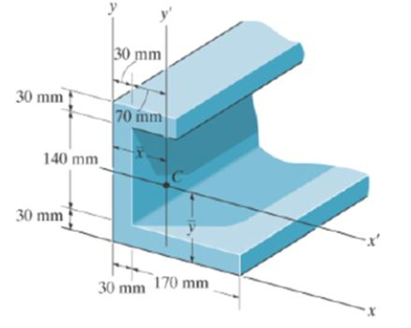
Chapter 10.4, Problem 45P
Determine the distance ˉx to the centroid C of the beam’s cross-sectional area and then compute the moment of inertia ¯Iy' about the y′ axis.
Expert Solution & Answer
Want to see the full answer?
Check out a sample textbook solution
Students have asked these similar questions
Using a AutoCAD drawing the section view for the following multiview drawing
Can you help me by providing the MATLAB code?
The figure illustrates the nonpermanent connection of a steel cylinder head to a grade 30 cast-iron pressure vessel using
73 bolts. A confined gasket seal has an effective sealing diameter D of 0.9 m. The cylinder pressure is cycled between a
minimum pressure of zero and a maximum pressure p, of 535 kPa. For the specifications given in the table for the
specific problem assigned, select a suitable bolt length from the preferred sizes. Use Table A-17 for calculation purposes.
Parameter
Head thickness, A
Cylinder thickness, B
Value
16 mm
25 mm
Internal diameter of the cylinder, C
0.8 m
Gasket sealing diameter, D
Bolt circle diameter, E
Outer diameter of the cylinder head, F
0.9 m
1.0 m
1.1 m
Bolt grade
ISO 10.9
Bolt diameter, d
10 mm
F
E
D
111
Find a suitable bolt length. Then, determine the bolt stiffness, material stiffness and stiffness constant of the joint.
The bolt length is
The bolt stiffness is
mm.
MN/m.
The material stiffness is |
The stiffness constant is
MN/m.
Chapter 10 Solutions
Engineering Mechanics: Statics
Ch. 10.3 - Determine the moment of inertia of the shaded area...Ch. 10.3 - Determine the moment of inertia of the shaded area...Ch. 10.3 - Determine the moment of inertia of the shaded area...Ch. 10.3 - Determine the moment of inertia of the shaded area...Ch. 10.3 - Prob. 1PCh. 10.3 - Prob. 2PCh. 10.3 - Prob. 3PCh. 10.3 - Prob. 4PCh. 10.3 - Prob. 5PCh. 10.3 - Prob. 6P
Ch. 10.3 - Prob. 7PCh. 10.3 - Prob. 8PCh. 10.3 - Determine the moment of inertia of the area about...Ch. 10.3 - Solve the problem in two ways, using rectangular...Ch. 10.3 - Prob. 11PCh. 10.3 - Prob. 12PCh. 10.3 - Prob. 13PCh. 10.3 - Prob. 14PCh. 10.3 - Prob. 15PCh. 10.3 - Prob. 16PCh. 10.3 - Prob. 17PCh. 10.3 - Prob. 18PCh. 10.3 - Prob. 19PCh. 10.3 - Prob. 20PCh. 10.3 - Prob. 21PCh. 10.3 - Prob. 22PCh. 10.3 - Prob. 23PCh. 10.3 - Prob. 24PCh. 10.4 - Determine the moment of inertia of the beams...Ch. 10.4 - Determine the moment of inertia of the beams...Ch. 10.4 - Determine me moment of inertia of the...Ch. 10.4 - Determine the moment of inertia of the...Ch. 10.4 - Determine the moment of inertia of the composite...Ch. 10.4 - Determine the moment of inertia of the composite...Ch. 10.4 - Prob. 27PCh. 10.4 - Prob. 28PCh. 10.4 - Prob. 29PCh. 10.4 - Prob. 30PCh. 10.4 - Prob. 31PCh. 10.4 - Prob. 32PCh. 10.4 - Prob. 33PCh. 10.4 - Determine the moment of inertia of the beams...Ch. 10.4 - Determine, g, which locates the centroidal axis z...Ch. 10.4 - Prob. 36PCh. 10.4 - Prob. 37PCh. 10.4 - Prob. 38PCh. 10.4 - Prob. 39PCh. 10.4 - Prob. 41PCh. 10.4 - Determine the moment of inertia of the beams...Ch. 10.4 - Prob. 43PCh. 10.4 - Prob. 44PCh. 10.4 - Determine the distance x to the centroid C of the...Ch. 10.4 - Determine the moment of inertia of the area about...Ch. 10.4 - Determine the moment of inertia of the area about...Ch. 10.4 - Prob. 50PCh. 10.4 - Prob. 51PCh. 10.4 - Determine the moment of inertia of the...Ch. 10.4 - Determine the moment of inertia of the...Ch. 10.7 - Determine the product of inertia of the thin strip...Ch. 10.7 - Prob. 55PCh. 10.7 - Determine the product of inertia of the shaded...Ch. 10.7 - Prob. 57PCh. 10.7 - Determine the product of inertia of the shaded...Ch. 10.7 - Prob. 59PCh. 10.7 - Prob. 60PCh. 10.7 - Prob. 62PCh. 10.7 - Determine the product of inertia for the beams...Ch. 10.7 - Prob. 64PCh. 10.7 - Prob. 65PCh. 10.7 - Determine the product of inertia of the cross...Ch. 10.7 - Prob. 67PCh. 10.7 - For the calculation, assume all comers to be...Ch. 10.7 - Prob. 69PCh. 10.7 - Prob. 70PCh. 10.7 - Prob. 71PCh. 10.7 - Prob. 72PCh. 10.7 - Prob. 73PCh. 10.7 - Prob. 74PCh. 10.7 - Prob. 75PCh. 10.7 - Prob. 76PCh. 10.7 - Prob. 77PCh. 10.7 - Prob. 78PCh. 10.7 - Prob. 79PCh. 10.7 - Prob. 80PCh. 10.7 - Prob. 81PCh. 10.7 - Prob. 82PCh. 10.7 - using Mohrs circle.Ch. 10.8 - Determine the moment of inertia of the thin ring...Ch. 10.8 - The material has a constant density .Ch. 10.8 - Prob. 86PCh. 10.8 - Determine the radius of gyration kx of the...Ch. 10.8 - The material has a constant density .Ch. 10.8 - Hint: For integration, use thin plate elements...Ch. 10.8 - Prob. 90PCh. 10.8 - Prob. 91PCh. 10.8 - Determine the moment of inertia Iy. The specific...Ch. 10.8 - Prob. 93PCh. 10.8 - The total mass of the solid is 1500 kg.Ch. 10.8 - Prob. 95PCh. 10.8 - Prob. 96PCh. 10.8 - Determine the location y of the center of mass G...Ch. 10.8 - Prob. 98PCh. 10.8 - 15 lb. and 20 lb, respectively, determine the mass...Ch. 10.8 - The density of the material is 7.85 Mg/m3.Ch. 10.8 - The material has a density of 200kg/m3. Prob....Ch. 10.8 - The pendulum consists of a plate having a weight...Ch. 10.8 - Prob. 103PCh. 10.8 - The material has a density of 200kg/m3.Ch. 10.8 - Prob. 105PCh. 10.8 - Determine its mass moment of inertia about the y...Ch. 10.8 - Prob. 107PCh. 10.8 - Prob. 108PCh. 10.8 - Prob. 109PCh. 10.8 - Determine the moment of inertia for the shaded...Ch. 10.8 - Prob. 111RPCh. 10.8 - Determine the product of inertia of the shaded...Ch. 10.8 - Determine the area moment of inertia of the...Ch. 10.8 - Determine the area moment of inertia of the shaded...Ch. 10.8 - Determine the moment of inertia for the shaded...Ch. 10.8 - Prob. 117RPCh. 10.8 - Prob. 119RP
Knowledge Booster


Learn more about
Need a deep-dive on the concept behind this application? Look no further. Learn more about this topic, mechanical-engineering and related others by exploring similar questions and additional content below.Similar questions
- Problem 3 A rotating shaft of 20 mm diameter is simply supported. The shaft is loaded with a transverse load of 10 kN as shown in the figure. The shaft is made from AISI 1095 hot-rolled steel. The surface has been machined. The shaft operate at temperature T = 450 °C. Consider a reliability factor of 95%. Determine (a) Calculate the reaction forces R₁ and R2* (b) Draw the shear force and bending moment diagrams and determine the maximum bending moment and shear force. 200 mm 20 mm 10,000 N -50 mm- C A B R₁ Not to scale. (c) Determine the critical location of the shaft and the maximum effective stresses, (d) Calculate the static safety factor against yielding. (e) Determined the endurance limit, adjusted as necessary with Marin factors. (f) Calculate the fatigue factor of safety based on achieving infinite life (g) If the fatigue factor of safety is less than 1, then estimate the life of the part in number of rotations, based on the ultimate strength of the material at T = 450 °C.arrow_forwardAn air duct heater consists of an aligned array of electrical heating elements in which the longitudinal and transverse pitches are SL = ST = 24 mm. There are 3 rows of elements in the flow direction (NL = 3) and 4 elements per row (NT = 4). Atmospheric air with an upstream velocity of 12 m/s and a temperature of 25°C moves in cross flow over the elements, which have a diameter of 12 mm, a length of 250 mm, and are maintained at a surface temperature of 350°C. (a) Determine the total rate of heat transfer to the air and the temperature of the air leaving the duct heater. (b) Determine the pressure drop across the element bank and the fan power requirement. (c) Compare the average convection coefficient obtained in your analysis with the value for an isolated (single) element. Explain the difference between the results. (d) What effect would increasing the longitudinal and transverse pitches to 30 mm have on the exit temperature of the air, the total heat rate, and the…arrow_forwardWhat is the elongation of the rod in inches? And what is the change in diameter? I dont want either answer rounded please! Thank you.arrow_forward
- Draw the shear and bending-moment diagrams for the beam and loading shown, and determine the maximum absolute value of (a) the shear, (b) the bending moment. 300 lb 240 lb 360 lb C D E A 4 in. 3 in. 4 in. 5 in. Fig. P12.5arrow_forwardA commercial office building is located in the city of Lansing, Michigan, and is heatedusing a gaseous fuel with a heating value of 725 Btu/std ft3. The indoor designtemperature is 71ºF. The heat load for the building is known to be 250,000 Btu/hr. Thisheat load accounts for the fact that there are internal heat gains in the building, due tothe presence of people and electronic equipment (e.g., lights and radios). People in thebuilding are usually seated and involved in light activity.a) The furnace had an initial efficiency factor of 73% when installed, but since thenefficiency-improvement retrofits were implemented that raised the efficiency factorto its present value of 82%. The building was designed using the 99% designheating temperature value for the city to determine the outdoor design temperature.Evaluate the annual fuel quantity (in std ft3) required to heat the building, using thedegree-day or bin method.b) Seventy people use the building, but the occupancy pattern for the…arrow_forwardThe volumetric flow rate of air through a duct transition of the type shown in Table 12-9b (rectangular with two parallel sides) is 2 m3/s. The duct before the transition issquare, with a height of 50 cm. The expansion ratio across the transition is 4 (i.e., theduct area after the transition is 4 times greater than the duct area before the transition).a) Determine the pressure loss (in Pa) across the transition if the exit from the duct isabrupt (i.e., the diverging angle of the transition is 180º).b) Determine the percentage reduction in pressure loss for a transition diverging angleof 20º compared to the one in part (a).c) The head HVAC engineer requires the pressure loss across the transition to bereduced to less than 50% of the pressure loss for an abrupt exit (i.e., the case in part(a)), and suggests a transition diverging angle of 45º. Will this new diverging angleachieve the required reduction in pressure loss? Justify your answer.d) For a transition diverging angle of 90º, the…arrow_forward
- The volumetric flow rate of air through a duct transition of the type shown in Table 12-9b (rectangular with two parallel sides) is 2 m3/s. The duct before the transition issquare, with a height of 50 cm. The expansion ratio across the transition is 4 (i.e., theduct area after the transition is 4 times greater than the duct area before the transition).a) Determine the pressure loss (in Pa) across the transition if the exit from the duct isabrupt (i.e., the diverging angle of the transition is 180º).b) Determine the percentage reduction in pressure loss for a transition diverging angleof 20º compared to the one in part (a).c) The head HVAC engineer requires the pressure loss across the transition to bereduced to less than 50% of the pressure loss for an abrupt exit (i.e., the case in part(a)), and suggests a transition diverging angle of 45º. Will this new diverging angleachieve the required reduction in pressure loss? Justify your answer.d) For a transition diverging angle of 90º, the…arrow_forwardAuto Controls The figure is a schematic diagram of an aircraft elevator control system. The input to the systemin the deflection angle of the control lever , and the output is the elevator angle phi.show that for each angle theta of the control lever ,there is a corresponding elevator angle phi. Then find Y(s)/theta(s) and simplify the resulting transfer function . Also note from the diagram that y and phi is related Show full solution, no copied solutionsarrow_forwardhand-written solutions only. correct answers upvotedarrow_forward
- For a small house located in Ottawa, Ontario, there are three windows and three doors.You are assigned the task of determining the infiltration and related heat loss rates.It has been found experimentally that the pressure difference due to pressurization is -0.002 in. water. The pressure difference due to stack effect for this building is assumednegligible due to it having only a single floor. The dominant mean wind speed fordesign is assumed to be 15 mph. The house orientation is such that it is normal to thedominant mean wind direction.The house was built recently and all of the windows and doors are tight fitting. Thehouse construction and materials are typical for Ottawa, Ontario. The doors are 3 ftwide and 6.75 ft high. Each of the windows is double hung and each window has thefollowing overall dimensions: 3 ft wide and 4 ft high. (For clarity it is noted that eachdouble hung window has two glass segments that are 3 ft wide and 2 ft high.)The indoor design temperature is 70ºF and…arrow_forwardH.W1: Due to the applied loading, the element at point A on the solid cylinder is subjected to the state of stress shown. Determine the principal 6 ksi stresses acting at this point. 12 ksiarrow_forwardA wall is 7 m wide and 3 m high, and contains two doors and one window. Details onthe wall components are as follows:• The window is a triple-glazed glass window with a 6.4 mm space filled withargon gas. The window surfaces do not have any special surface emissivitycoatings. The window dimensions are 2 m by 1 m, and the window has analuminum sash with a thermal break.• The wall material has an overall heat-transfer coefficient of 0.5 W/(m2-ºC).• Each door is a solid core flush door made of wood, with a thickness of 4.5 cm.Also, each door is 2.1 m high and 0.8 m wide. Both doors are accompanied bymetal storm doors.a) Determine the overall heat-transfer coefficient [in W/(m2-ºC)] for the wallcombination (based on the overall dimensions of the wall-window-doorscombination), assuming winter conditions.b) The room is maintained at a temperature of 22ºC. If the heat flow rate through thewall is 0.4 kW at a certain time, what is the outdoor temperature at that time?Infiltration can be…arrow_forward
arrow_back_ios
SEE MORE QUESTIONS
arrow_forward_ios
Recommended textbooks for you
 International Edition---engineering Mechanics: St...Mechanical EngineeringISBN:9781305501607Author:Andrew Pytel And Jaan KiusalaasPublisher:CENGAGE L
International Edition---engineering Mechanics: St...
Mechanical Engineering
ISBN:9781305501607
Author:Andrew Pytel And Jaan Kiusalaas
Publisher:CENGAGE L
moment of inertia; Author: NCERT OFFICIAL;https://www.youtube.com/watch?v=A4KhJYrt4-s;License: Standard YouTube License, CC-BY