
Concept explainers
Videos
In the op amp circuit of Fig. 10.118, find the closed-loop gain and phase shift of the output voltage with respect to the input voltage if C1 = C2 = 1 nF, R1 = R2 = 100 kΩ, R3 = 20 kΩ R4 = 40 kΩ and ω = 2000 rad/s.
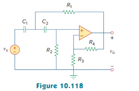
Calculate the closed-loop gain and phase shift of the output voltage of the op amp circuit in Figure 10.118 using MATLAB.
Answer to Problem 75P
The closed-loop gain and phase shift of the output voltage are
Explanation of Solution
Given data:
Refer to Figure 10.118 in the textbook for op amp circuit.
The value of angular frequency
Formula used:
Write the expression to calculate impedance of the capacitor.
Here,
Calculation:
Let us assume that source voltage
Substitute
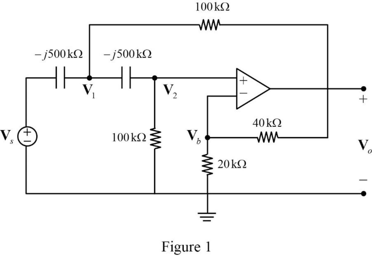
The frequency domain representation of given figure is shown in Figure 1.
Apply Kirchhoff’s current law at node
Substitute
Apply Kirchhoff’s current law at node
Apply voltage division rule at node
According to the properties of ideal op amp, the voltage at the input of the non-inverting terminal of the op amp is equal to the voltage at the input of the inverting terminal. Hence,
Substitute equation (5) in (2).
Substitute equation (5) in (3).
Represent the equations (6) and (7) in matrix form.
The MATLAB code to solve equation (8) is shown below.
A = [1+0.4*i -1-0.0667*i; 1 -0.3333+1.6667*i];
b = [2*i; 0];
x = A\b
The MATLAB result is shown below.
x =
-0.4166 + 2.0833i -1.2499 - 0.0000i
The polar representation of obtained results is shown below.
Write the expression for closed loop gain.
Substitute
Conclusion:
Thus, the closed-loop gain and phase shift of the output voltage are
Want to see more full solutions like this?
Chapter 10 Solutions
EBK FUNDAMENTALS OF ELECTRIC CIRCUITS


- 2. During + input cycle, it has an output signal voltage, at the negative input cycle, the output experiences a negative current surge at the inductor and causes the circuit to explode. What could be wrong in the circuit? Explain. Q1 R1 1kQ D1 V2 1kHz 5V L1 V1 1mH 12Varrow_forwardQ2) design a wien bridge to produce an output sinusoid that can be adjusted from 400 Hz to 100 kHz assuming a capacitor equal to 0.01uF.arrow_forwardThe behavior of oscillator is described by Olong periods of dissipation followed by short impulses Oshort periods of dissipation followed by short impulses Olong periods of dissipation followed by long impulses ONone of the abovearrow_forward
- for the RC oscillator circuit shown with C = 1 nF and R = 1 KΩ answer the following:1. Find the value of Rf and Ri to start oscillation2. What is the phase shift of each RC-section if there is 6 RC-sections3. For the same frequency of oscillation design another RC oscillator circuit usingnon-inverting configuration of Op-amparrow_forwardAn ideal ac current source is applied to the input terminals of an amplifier, and the amplifier output voltage is 2 V rms. Then, a 2-kΩ resistance is placed in parallel with the current source and the amplifier input terminals, and the output voltage is 1.5 V rms. Determine the input resistance of the amplifier.arrow_forwardConsider the op amp circuit below to be ideal. Find the input resistance Rin. 98k 2 2k 2 ww VỊ OWW 10k2arrow_forward
- Determine the output voltage of an op amp amplifier circuit with the following parameters: Differential voltage gain = 4522CMRR = 631Vi1 = 659 mV Vi2 = 659 mV Vi1 and Vi2 are in phase and have the same frequency. \ QUICKLYarrow_forwardPerform an AC analysis for the following circuit. Show the waveform measured at the OUTPUT from 10 Hz to 100 kHz. +A V2 + V3 12 12 -V- Inverting Amplifier Circuit +Vin V1 R1 100 SINE(0 2 500) R2 200 -V+ U1 LT1028 OUTPUTarrow_forwardthis is CC(common collecter ) amplifier.why it is a cc circuit, you can get the answer from its AC circuit.so now PLS draw its AC and DC circuit. plz solve it earlyarrow_forward
- A student is working operational amplifier in such a way that performs an integrator and differentiator respectively. if input voltage 100 sin volt is applied of both amplifier at inverting terminal keeping non invertional terminal grounded then find the following using same input voltage. 1. Analyze the nature of output voltage of differentiator. a) It converts pulse waveform into square waveform. b) it converts square waveform triangular waveform. c) It converts square waveform into pulse waveform. d) it converts triangular waveform into square waveform. 1. Analyze the nature of output voltage of integrator a) It converts square waveform into triangular waveform b) It converts triangular waveform into square waveform c) It converts pulse waveform into square waveform d) It converts square waveform into pulse waveformarrow_forwardIn the given circuit what is the derivation formula for the magnitude of vf/vo and by using this formula solve for the required gain of the op amp and the required resistance rf to sustain the oscillation. Given: Rr = 15 kΩ C1 = 2.2 nF C2 = 4.7 nF R1 = 47 kΩ R2 = 22 kΩarrow_forwardCE Amp with pnp transistor VEE= = 12V RE 13k2 pnp B=l00 R2 look CE VA = O %3D Ri : G Rout Ike C2 RIN 300kr Re RL Vo 43k2 43 k2 Find: O) max to avoid small Signal distortion ) max Vi to awidgoutput noltage ongadistorihim eliping in thearrow_forward
 Introductory Circuit Analysis (13th Edition)Electrical EngineeringISBN:9780133923605Author:Robert L. BoylestadPublisher:PEARSON
 Delmar's Standard Textbook Of ElectricityElectrical EngineeringISBN:9781337900348Author:Stephen L. HermanPublisher:Cengage Learning
 Programmable Logic ControllersElectrical EngineeringISBN:9780073373843Author:Frank D. PetruzellaPublisher:McGraw-Hill Education
 Fundamentals of Electric CircuitsElectrical EngineeringISBN:9780078028229Author:Charles K Alexander, Matthew SadikuPublisher:McGraw-Hill Education
 Electric Circuits. (11th Edition)Electrical EngineeringISBN:9780134746968Author:James W. Nilsson, Susan RiedelPublisher:PEARSON
 Engineering ElectromagneticsElectrical EngineeringISBN:9780078028151Author:Hayt, William H. (william Hart), Jr, BUCK, John A.Publisher:Mcgraw-hill Education,