
Videos
The steady-state error due to a unit-ramp command and due to a unit-ramp disturbance of I controller with an internal feedback loop of first order plant for the given cases.
Answer to Problem 10.28P
The steady-state error values for all the cases are:
Case 1. For ζ=0.707 ,
Error due to unit-ramp command: ess=0.2
Error due to unit-ramp disturbance: ess=0.005
Case 2. For ζ=1 ,
Error due to unit-ramp command: ess=0.4
Error due to unit-ramp disturbance: ess=0.01
Case 3. For a root separation factor of 10,
Error due to unit-ramp command: ess=0.22
Error due to unit-ramp disturbance: ess=0.001.
Explanation of Solution
Given:
The I controller with an internal feedback loop of first order plant is as shown below:
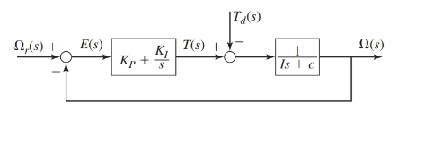
Where, the parameter values are as given:
I=c=4
Also, the performance specifications require the time constant of the system to be τ=0.2 .
The values of gains for the I controller are as follows:
Case 1. For ζ=0.707, KI=200 and K2=36.
Case 2. For ζ=1, KI=100 and K2=36.
Case 3. For a root separation factor of 10, KI=1000 and K2=216.
Concept Used:
- The transfer functions for the block diagram are as shown below:
- The steady-state error of a system using final value theorem is:
Ω(s)Ωr(s)=KIIs2+s(c+K2)+KIΩ(s)Td(s)=−sIs2+s(c+K2)+KI
ess=lims→0sE(s).
Calculation:
From the block diagram as shown, the transfer functions are as:
Ω(s)Ωr(s)=KIIs2+s(c+K2)+KIΩ(s)Td(s)=−sIs2+s(c+K2)+KI
Therefore, the response Ω(s) for the system is:
Ω(s)=KIIs2+s(c+K2)+KIΩr(s)−sIs2+s(c+K2)+KITd(s)
And from the block diagram shown in figure, we have
E(s)=(Ωr(s)−Ω(s))⇒E(s)=(1−KIIs2+s(c+K2)+KI)Ωr(s)+sIs2+s(c+K2)+KITd(s)∵Ω(s)=KIIs2+s(c+K2)+KIΩr(s)−sIs2+s(c+K2)+KITd(s)
On keeping the values of the parameters such that I=c=4
E(s)=(1−KIIs2+s(c+K2)+KI)Ωr(s)+sIs2+s(c+K2)+KITd(s)⇒E(s)=(s(Is+c+K2)Is2+s(c+K2)+KI)Ωr(s)+sIs2+s(c+K2)+KITd(s)⇒E(s)=(s(4s+4+K2)4s2+s(4+K2)+KI)Ωr(s)+s4s2+s(4+K2)+KITd(s)
Case 1. When ζ=0.707, the gain values are KI=200 and K2=36:
Since,
E(s)=(s(4s+4+K2)4s2+s(4+K2)+KI)Ωr(s)+s4s2+s(4+K2)+KITd(s)∵KI=200 and K2=36⇒E(s)=(s(4s+4+36)4s2+s(4+36)+200Ωr(s)+s4s2+s(4+36)+200Td(s))⇒E(s)=(s(4s+40)4s2+40s+200Ωr(s)+s4s2+40s+200Td(s))
Therefore, for unit-ramp command response Ωr(s) and zero disturbance torque Td(s), we have
E(s)=(s(4s+40)4s2+40s+200Ωr(s)+s4s2+40s+200Td(s))⇒E(s)=(s(4s+40)4s2+40s+200⋅1s2+s4s2+40s+200⋅0)⇒E(s)=(4s+40)(4s2+40s+200)⋅1s⇒E(s)=(s+10)(s2+10s+50)⋅1s
Thus, the steady-state error for this design is:
ess=lims→0sE(s)⇒ess=lims→0s(s+10)(s2+10s+50)⋅1s∵E(s)=(s+10)(s2+10s+50)⋅1s⇒ess=lims→0(s+10)(s2+10s+50)=1050⇒ess=0.2
Therefore, for zero command response Ωr(s) and unit-ramp disturbance torque Td(s), we have
E(s)=(s(4s+40)4s2+40s+200Ωr(s)+s4s2+40s+200Td(s))⇒E(s)=(s(4s+40)4s2+40s+200⋅0+s4s2+40s+200⋅1s2)⇒E(s)=1(4s2+40s+200)⋅1s⇒E(s)=14(s2+10s+50)⋅1s
Thus, the steady-state error for this design is:
ess=lims→0sE(s)⇒ess=lims→0s14(s2+10s+50)⋅1s∵E(s)=14(s2+10s+50)⋅1s⇒ess=lims→014(s2+10s+50)=1200⇒ess=0.005
Case 2. When ζ=1, the gain values are KI=100 and K2=36:
Since,
E(s)=(s(4s+4+K2)4s2+s(4+K2)+KI)Ωr(s)+s4s2+s(4+K2)+KITd(s)∵KI=100 and K2=36⇒E(s)=(s(4s+4+36)4s2+s(4+36)+100Ωr(s)+s4s2+s(4+36)+100Td(s))⇒E(s)=(s(4s+40)4s2+40s+100Ωr(s)+s4s2+40s+100Td(s))
Therefore, for unit-ramp command response Ωr(s) and zero disturbance torque Td(s), we have
E(s)=(s(4s+40)4s2+40s+100Ωr(s)+s4s2+40s+100Td(s))⇒E(s)=(s(4s+40)4s2+40s+100⋅1s2+s4s2+40s+100⋅0)⇒E(s)=(4s+40)(4s2+40s+100)⋅1s⇒E(s)=(s+10)(s2+10s+25)⋅1s
Thus, the steady-state error for this design is:
ess=lims→0sE(s)⇒ess=lims→0s(s+10)(s2+10s+25)⋅1s∵E(s)=(s+10)(s2+10s+25)⋅1s⇒ess=lims→0(s+10)(s2+10s+25)=1025⇒ess=0.4
Therefore, for zero command response Ωr(s) and unit-ramp disturbance torque Td(s), we have
E(s)=(s(4s+40)4s2+40s+100Ωr(s)+s4s2+40s+100Td(s))⇒E(s)=(s(4s+40)4s2+40s+100⋅0+s4s2+40s+100⋅1s2)⇒E(s)=1(4s2+40s+100)⋅1s⇒E(s)=14(s2+10s+25)⋅1s
Thus, the steady-state error for this design is:
ess=lims→0sE(s)⇒ess=lims→0s14(s2+10s+25)⋅1s∵E(s)=14(s2+10s+25)⋅1s⇒ess=lims→014(s2+10s+25)=1100⇒ess=0.01
Case 3. For a root separation factor of 10, KI=1000 and K2=216.
Since,
E(s)=(s(4s+4+K2)4s2+s(4+K2)+KI)Ωr(s)+s4s2+s(4+K2)+KITd(s)∵KI=1000 and K2=216⇒E(s)=(s(4s+4+216)4s2+s(4+216)+1000Ωr(s)+s4s2+s(4+216)+1000Td(s))⇒E(s)=(s(4s+220)4s2+220s+1000Ωr(s)+s4s2+220s+1000Td(s))
Therefore, for unit-ramp command response Ωr(s) and zero disturbance torque Td(s), we have
E(s)=(s(4s+220)4s2+220s+1000Ωr(s)+s4s2+220s+1000Td(s))⇒E(s)=(s(4s+220)4s2+220s+1000⋅1s2+s4s2+220s+1000⋅0)⇒E(s)=(4s+220)(4s2+220s+1000)⋅1s⇒E(s)=(s+55)(s2+55s+250)⋅1s
Thus, the steady-state error for this design is:
ess=lims→0sE(s)⇒ess=lims→0s(s+55)(s2+55s+250)⋅1s∵E(s)=(s+55)(s2+55s+250)⋅1s⇒ess=lims→0(s+55)(s2+55s+250)=55250⇒ess=0.22
Therefore, for zero command response Ωr(s) and unit-ramp disturbance torque Td(s), we have
E(s)=(s(4s+220)4s2+220s+1000Ωr(s)+s4s2+220s+1000Td(s))⇒E(s)=(s(4s+220)4s2+220s+1000⋅0+s4s2+220s+1000⋅1s2)⇒E(s)=1(4s2+220s+1000)⋅1s⇒E(s)=14(s2+55s+250)⋅1s
Thus, the steady-state error for this design is:
ess=lims→0sE(s)⇒ess=lims→0s14(s2+55s+250)⋅1s∵E(s)=14(s2+55s+250)⋅1s⇒ess=lims→0(s+1)4(s2+55s+250)=11000⇒ess=0.001.
Conclusion:
The steady-state error values for all the cases are:
Case 1. For ζ=0.707 ,
Error due to unit-ramp command: ess=0.2
Error due to unit-ramp disturbance: ess=0.005
Case 2. For ζ=1, Tm≈35 N⋅m.
Error due to unit-ramp command: ess=0.4
Error due to unit-ramp disturbance: ess=0.01
Case 3. For a root separation factor of 10, Tm≈215 N⋅m.
Error due to unit-ramp command: ess=0.22
Error due to unit-ramp disturbance: ess=0.001.
Want to see more full solutions like this?
Chapter 10 Solutions
System Dynamics


- Tribobolgy 15/2022 Monthly Exam. Automobile Eng. Dert 2nd Semster/3rd class Max. Mark: 100% 7. Viscosity of multi-grade oils (a) Reduces with temperature (c) is less sensitive to temperature (b) Increases with temperature (d) None of the above 8. In a hydrodynamic journal bearing if eccentricity ratio = 1, it means (a) Journal/shaft is subjected to no load and the rotational speed is very high. (b) Journal is subjected to no load and the rotational speed is moderate (c) Journal is subjected to very light load and the rotational speed is very high. (d) Journal is subjected to very high load and the rotational speed is negligible. Q4/ The journal speed of a 100mm diameter journal is 2500 rpm. The journal is supported by a short hydrodynamic bearing of length L=0.6D, eccentricity ratio = 0.75 and a clearance ratio C/R=0.001. The radial load on the bearing is 10 kN. The lubricant is SAE 30, and the operating temperature of the lubricant in the bearing is 700C. 1- Assume…arrow_forward1 of 2 Monthly Exam. Automobile Eng. Dert 2nd Semster/3rd class Max. Mark: 100% Q1/A/ Compare between the long and short journal bearings B/ With the help of Stribeck's curve, discuss different regimes of lubrication. C/ Explain the importance of Tribology in the design of different machine elements Q2 /A/ According to the SAE viscosity grading system all engine oils are divided into two classes: monograde and multi-grade. Compare between them? B/What are the differences between grease and Synthetic oils C/ Explain the effect of eccentricity ratio & with respect to hydrodynamic journal bearing. Q3/A/ What are the major factors which affect the selection of lubricants? B/What are the criteria to classify sliding bearings? C/ Answer of the following: 1. According to the SAE viscosity classification, the oil (SAE 40) is lower viscosity than the oil (SAE 20) at the same temperature. (True or False) 2. For a slow speed-highly loaded bearing, used oils of high viscosity; while for high-speed…arrow_forwardThe uniform rods have a mass per unit length of 10kg/m . (Figure 1)If the dashpot has a damping coefficient of c=50N⋅s/m , and the spring has a stiffness of k=600N/m , show that the system is underdamped, and then find the pendulum's period of oscillation.arrow_forward
- 10-50. The principal plane stresses and associated strains in a plane at a point are σ₁ = 30 ksi, σ₂ = -10 ksi, e₁ = 1.14(10-3), €2=-0.655(103). Determine the modulus of elasticity and Poisson's ratio. emps to plum... Wednesday FI a וח 2 Q Search 48 F5 - F6 4+ F7 FB F9 FIO FII F12 & * S 6 7 8 9 ㅁ F2 # *F3 3 $ 4 F4 % W E R T Y ப S ALT D F G H X C V B N J Σ H L ว { P [ ] ALT " DELETE BACKSPACE NUM LOCK T 7 HOME ENTER 4 PAUSE SHIFT CTRL Earrow_forward10−9. The state of strain at the point has components of ϵx = −100(10−6), ϵy = −200(10−6), and γxy=100(10−6). Use the strain transformation equations to determine (a) the in-plane principal strains and (b) the maximum in-plane shear strain and average normal strain. In each case specify the orientation of the element and show how the strains deform the element within the x−y plane.arrow_forwardThe strain gage is placed on the surface of the steel boiler as shown. If it is 0.5 in. long, determine the pressure in the boiler when the gage elongates 0.2(10−3) in. The boiler has a thickness of 0.5 in. and inner diameter of 60 in. Also, determine the maximum x, y in-plane shear strain in the material. Take Est=29(103)ksi, vst=0.3.arrow_forward
- (read image, answer given)arrow_forward6/86 The connecting rod AB of a certain internal-combustion engine weighs 1.2 lb with mass center at G and has a radius of gyration about G of 1.12 in. The piston and piston pin A together weigh 1.80 lb. The engine is running at a constant speed of 3000 rev/min, so that the angular velocity of the crank is 3000(2)/60 = 100л rad/sec. Neglect the weights of the components and the force exerted by the gas in the cylinder compared with the dynamic forces generated and calculate the magnitude of the force on the piston pin A for the crank angle 0 = 90°. (Suggestion: Use the alternative moment relation, Eq. 6/3, with B as the moment center.) Answer A = 347 lb 3" 1.3" B 1.7" PROBLEM 6/86arrow_forward6/85 In a study of head injury against the instrument panel of a car during sudden or crash stops where lap belts without shoulder straps or airbags are used, the segmented human model shown in the figure is analyzed. The hip joint O is assumed to remain fixed relative to the car, and the torso above the hip is treated as a rigid body of mass m freely pivoted at O. The center of mass of the torso is at G with the initial position of OG taken as vertical. The radius of gyration of the torso about O is ko. If the car is brought to a sudden stop with a constant deceleration a, determine the speed v relative to the car with which the model's head strikes the instrument panel. Substitute the values m = 50 kg, 7 = 450 mm, r = 800 mm, ko = 550 mm, 0 = 45°, and a = 10g and compute v. Answer v = 11.73 m/s PROBLEM 6/85arrow_forward
- Using AutoCADarrow_forward340 lb 340 lb Δarrow_forward4. In a table of vector differential operators, look up the expressions for V x V in a cylindrical coordinate system. (a) Compute the vorticity for the flow in a round tube where the velocity profile is = vo [1-(³] V₂ = Vo (b) Compute the vorticity for an ideal vortex where the velocity is Ve= r where constant. 2πг (c) Compute the vorticity in the vortex flow given by Ve= r 2лг 1- exp ( r² 4vt (d) Sketch all the velocity and vorticity profiles.arrow_forward
 Elements Of ElectromagneticsMechanical EngineeringISBN:9780190698614Author:Sadiku, Matthew N. O.Publisher:Oxford University Press
 Mechanics of Materials (10th Edition)Mechanical EngineeringISBN:9780134319650Author:Russell C. HibbelerPublisher:PEARSON
 Thermodynamics: An Engineering ApproachMechanical EngineeringISBN:9781259822674Author:Yunus A. Cengel Dr., Michael A. BolesPublisher:McGraw-Hill Education
 Control Systems EngineeringMechanical EngineeringISBN:9781118170519Author:Norman S. NisePublisher:WILEY
 Mechanics of Materials (MindTap Course List)Mechanical EngineeringISBN:9781337093347Author:Barry J. Goodno, James M. GerePublisher:Cengage Learning
 Engineering Mechanics: StaticsMechanical EngineeringISBN:9781118807330Author:James L. Meriam, L. G. Kraige, J. N. BoltonPublisher:WILEY