
Concept explainers
Videos
The value of the CT secondary current (I’) and VT secondary voltage (V’).
Answer to Problem 10.1P
Explanation of Solution
Given Information:
Calculation:
The secondary voltage of the voltage transformer (V’) is,
Substitute the values in the above equation,
Now, the current (I) entering the primary of the current transformer is,
On substituting the values in the above equation,
And get,
Here, the CT equivalent circuit is,
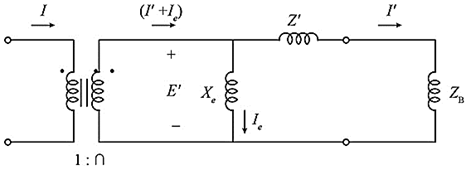
Fig: CT equivalent circuit diagram
Now, the secondary current of CT is,
Substituting the values in the above equation,
From the above equivalent circuit diagram, the secondary current consists of two components, there are
Whereas, I’ is the relay current and Ie is the exciting current.
CT error is Zero in the given question.
So that the exciting current is Zero, (Ie=0), therefore,
Want to see more full solutions like this?
Chapter 10 Solutions
MindTap Engineering, 1 term (6 months) Printed Access Card for Glover/Overbye/Sarma's Power System Analysis and Design, 6th


- Q2: For the circuit shown in below, use (matlab, c++, or python) and Nodal Analysis to: a) Find the voltage across the current source 11 terminals b) Find the current through the resistance R1 c) Find the real and reactive Powers delivered by the current source 11 Find the real and reactive Powers consumed by the capacitor C2 d) 11 10 A RMS 50 Hz +35 Deg Z1 AM R2 402 Z4 R4 80 m Z2 L2 15 mH 12 7A RMS 50 Hz +74 Deg Zc1 C1 150 F R3 30 www w R6 40 Z6 L3 25 mH E1 100 V RMS - 40 Deg Z5 50 Hz www R5 20 Zc2 C2 200 Farrow_forwardConsider two coupled dielectric slab waveguides .The two waveguides are identical to one another and have coupling coefficient:C=C12=C21=500 m-1 a)Find the length of the coupled waveguide structure that allows for complete power transfer from waveguide 1 to waveguide 2.b)Now assume that light is launched into both waveguides at the same power P0 and the same phase,but with linear X polarization in waveguide 1 and linear Y polarization in waveguide 2.Write expressions for the power and the polarization (normalized Jones vector)of the light in each waveguide as a function of the distance traveled.Assume that propagation constants and coupling coefficients are the same for both X and Y polarizations.arrow_forwardQUESTION 10 Consider a linear circuit having a single output voltage and two possible voltage sources as the input. Consider two situations: 1) Input voltage source #1 is equal to 4 Volts. Input voltage source #2 is equal to 3sin(60t) Volts. When both are applied, the output is 12+21cos(60t) Volts. 2) Input voltage source #1 is equal to 2 Volts. Input voltage source #2 is equal to 0. The corresponding outout is 6 Volts Then, if the input voltage source #1 is 0 and the input voltage source #2 is equal to 2cos(60t) Volts, the output is: a. 14cos(60t) Volts b. -6sin(60t) Volts c.-14sin(60t) Volts d. 21 cos(60t) Voltsarrow_forward
- Homework of Amplifier 1. Assume that a 600 2, 12 µV rms voltage source is driving the amplifier in Figure 1. Determine the overall voltage gain by taking into account the attenuation in the base circuit, and find the total output voltage (ac and de). What is the phase relationship of the collector signal voltage to the base signal voltage? Voc +18 V 3.3 kN C3 V R, 47 kN C, Vin 10 μF 10 μF BDC - 75 B = 70 Figure 1 RL 10 KN R. 12 kN RE 1.0 kN 10 μFarrow_forwardA TTL gate has the following actual voltage level values: VIH(min) = 2.25 V, VIL(max) = 0.65 V.Assuming it is being driven by a gate with VOH(min) = 2.4 V and VOL(max) = 0.4 V, what are the HIGH- and LOW-level noise margins?arrow_forward10. Fig. 9-14 shows a three-stage circuit with a Vcc supply of +20 V. GND stands for ground. If all transistors have a ß of 100, what are the Ic and VCE of each stage? + 20V 10µF 2kQ 3kQ 10µF 10µF 10μF 50ΚΩ Vo 100k2 :0.56kN 8kΩ 3kQ 0.68k2 GNDarrow_forward
- The current and voltage across a circuit element are given by the equations I(t) = 20e 100t (mA), V(t) = 105e-1⁰⁰t (V) Determine the total energy E dissipated by the element between t=0 and t=10ms. The instantaneous power dissipated by the element is P(t) = 1(t)V (t). Find the total energy E by integrating P(t) over the time interval from t=0 to t=10ms=0.01sec. To do so, use the function trapez(fn, a, b, h), which implements the trapezoidal rule for numerical integration and where fn is a function handle to a function that needs to be integrated, a and b are the integral limits and h is the step length. Write in Matlab the function that needs to be integrated and call function trapez with appropriate parameters.arrow_forwardQ.4 Referring to the system shown in Figure Q4 determine the values of K and k such that the system has a damping ratio 0.8, and an undumped natural frequency equal 4 rad/secarrow_forwardThe transfer function of a second order control system is Y(S) K C(s) S²+10S+ K Suppose that the input signal is the unit-step function and the value for k = 100. a. The undamped natural frequency b. The damping ratio c. The damped natural frequency o d. The roots of the characteristic equation. e. The maximum value of the gain k in order to have real negative roots of the characteristic equation. f. Sketch the response plot shown the maximum percent overshoot, peak time and settling time.arrow_forward
- 4- The data sheet of a quad two-input NAND gate specifies the following parameters: IoH (max.)=0.4 mA, VOH (min.) =2.7 V, VIH (min.) =2V, VIL (max.)=0.8 V, VOL (max.)=0.4 V, IOL (max.)=8 mA, IL (max.)=0.4 mA, IH (max.)=20µA, ICCH (max.)=1.6 mA, ICCL (max.)=4.4 mA, tpLH =tpHL=15 ns and a supply voltage range of 5 V. Determine (a) The average power dissipation of a single NAND gate, (b) The maximum average propagation delay of a single gate, (c) The HIGH-state noise margin and (d) the LOW-state noise marginarrow_forward5. In an RL circuit with a resistance of 175 Q and an inductor that has an inductive reactance value of 100 Q. Calculate the impedance and inductance of the circuit also draw the circuit diagram. Act Go tarrow_forwardExercises part: 1. For the circuit in Figure 1, determine and draw the Thevenin Equivalent circuit. Also, determine the current, I, and the power dissipated in the load. The load impedance Z, is changed as shown in table 2 when Z, = R- X, where Z, = R, ±X. Table 2 calculated values R, V. I. P, = 1, *V, 1.8- X, 2 10-X, 2 22 - х, 2 100 –X, 2 330- Х, 2 560 -X, 2 1-X, kQ 2.2-X, k2 10-X, k2 56-X, k2 2. Plot P, versus R, using Excel or MATLAB. It is required to figure out the maximum power transfer to the load. R 330 0 1 mH E = 5VZ 0° 1 uF f=1000HZ Figure 1.arrow_forward
 Operations Research : Applications and AlgorithmsComputer ScienceISBN:9780534380588Author:Wayne L. WinstonPublisher:Brooks Cole