
Concept explainers
Videos
The value of the CT secondary current (I’) and VT secondary voltage (V’).
Answer to Problem 10.1P
Explanation of Solution
Given Information:
Calculation:
The secondary voltage of the voltage transformer (V’) is,
Substitute the values in the above equation,
Now, the current (I) entering the primary of the current transformer is,
On substituting the values in the above equation,
And get,
Here, the CT equivalent circuit is,
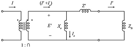
Fig: CT equivalent circuit diagram
Now, the secondary current of CT is,
Substituting the values in the above equation,
From the above equivalent circuit diagram, the secondary current consists of two components, there are
Whereas, I’ is the relay current and Ie is the exciting current.
CT error is Zero in the given question.
So that the exciting current is Zero, (Ie=0), therefore,
Want to see more full solutions like this?
Chapter 10 Solutions
Power System Analysis & Design


- Example 8.4 The one line diagram of a simple three-bus power system is shown in the figure. Each generator is j0.1 j0.2 represented by an emf behind the transient reactance. All impedances are expressed in per unit j0.1 j0.2 in a common 100 MVA base, and for simplicity, j0.8 resistances are neglected. The following assumption 2 are made: j0.4 j0.4 •shunt capacitances are neglected and the system is considered on no load. •all generators are running at their rated voltage 3 and rated frequency with their emf in phase Determine the fault current, the bus voltages and the line currents during the fault when a balanced three-phase fault with a fault impedance Z; = j0.16 %3D p.u. fault occurs on bus 3arrow_forwardThe VSWR on an 50-Ohm transmission line is 5. The distance between successive voltageminima is 80 cm while the distance from the load to the first minimum is 30 cm. What are thereflection coefficient and load impedancearrow_forwardDevelop a small-scale equivalent transmission line pi model (per phase) of the transmission lines with the specification given in table 1. The conductors are placed with a flat horizontal spacing of 7.25 meters. Consider that the load connected against the line 125MW at 0.85 lagging power factor. You are required to develop an equivalent model for a maximum 220V (RMS) sending and receiving end voltage and a maximum of 5A load current. Sr. NTDC Transmission Line Length Conductor No. Туре 220 kV DG Khan-Loralai Transmission Line (227 km) 227km Pheasant TABLE AJ Electrical characteristics of bare aluminum conductors steel-relnforced (ACSR)+ Reniertance Reactance per conductor 1-ft apacing. 60 Ha Ae, 60 Ha Capaitive Aluminum ares, emil Layers of Outaide aluminum diameter, in a/1,000 ft soC, D/ml GMR Induetive Stranding AL/8t De, 20°C. 20C, a/mi Code word D. t Ma-mi Waswing Partridge Ostrieh Merlin Linnet Oriole Chickndee Ibin Pelienn Flicker Hawk 266,800 206,800 300,000 336, 400 336.400…arrow_forward
- At the end of the 8 km overhead line given in the figure below, there are two distribution transformers, one of which is 800kVA and the other is 1200kVA, operated with power coefficients of 0.6 and 0.8, respectively. The end-of-line voltage is 6kV. Find the required rated cross section and line head voltage so that the power loss on the line is less than %pk = 10.arrow_forward6. For a three bus power system assume bus 1 is the swing with a per unit voltage of 1.020 , bus 2 is a PQ bus with a per unit load of 2.0 + j0:5, and bus 3 is a PV bus with 1.0 per unit generation and a 1.0 voltage setpoint. The per unit line impedances are j0.1 between buses 1 and 2, j0.4 between buses 1 and 3, and j0.2 between buses 2 and 3. Using a flat start, use the Newton-Raphson approach to determine the first iteration phasor voltages at buses 2 and 3.arrow_forward1.The voltage magnitude and phase angle are the quantities to be determined after load flow analysis for............. bus. 2.The total reactance of the transmission system is reduced by installing a series capacitor. Select one: True Falsearrow_forward
- Discuss the role of FACTS (Flexible Alternating Current Transmission Systems) devices in power system control and optimization.arrow_forward2) A 200 ohm resistive load will be matched to a So ohm resstive source impedance. a) Calalate the L-C poss and high pass lumped matching netuwork component Values (tuo sets of L-C vales) b) Sketch the impedonce matching netwark that can be constructed by connec tion of short line segmants. C Assume 15 ohm and 150 ahm characteristic impedance lines are auailable tine lengths for realaing Determine the coriesponding one of the Salutions in part ()arrow_forward9.23 A three- phase, 230-KV, 60HZ, comple tely Eranspesed transmissin line 1113-MCM horizontal spacing with 5M between adjacent has one conductor pes phase, and a flat con duc tors. 1. Calcula be the capacitance per phase in Plm and the admitbance pes phase in S lkm. 2. Calculate Ehe to tal churging by the transmission line caraci tance when it is 125km long and operatel at 345K V. current takenarrow_forward
- The sample large power system network data's are given below, The total number of buses is 5 Three-phase short circuit fault subjected at the bus 5 The initial voltage of the faulted bus is 1.0 p.u The Zbus matrix element Z55 is 0.704 p.u Fault impedance Zf= 0.33 p.u Fault current (If )in p.u ..........arrow_forwardfollowing figure shows the one-line diagram of a power system. Bus 1 is selected as a reference bus (slack bus), and bus 2 is load bus. Using the Gauss-Seidel method, determine the value of the voltage at the load bus 2 and perform two iteration. Moreover determine the complex power flow at bus 1 and also active and reactive power in transmission line. The line impedance on a base of 100 MVA. Use an initial estimate of V,º = 1+ j(0) . S1 Z12 = 0.02 + j0.04 2 S2 = 280 MW +j60 Mvararrow_forwardIn the T-Model method which among these are divided into two halves. a. Both (A) and (B) b. None of these c. Shunt capacitance d. Series impedancearrow_forward
 Power System Analysis and Design (MindTap Course ...Electrical EngineeringISBN:9781305632134Author:J. Duncan Glover, Thomas Overbye, Mulukutla S. SarmaPublisher:Cengage Learning