
CONTROL SYSTEMS ENGINEERING
7th Edition
ISBN: 9781119185666
Author: NISE
Publisher: WILEY
expand_more
expand_more
format_list_bulleted
Concept explainers
Videos
Textbook Question
Chapter 1, Problem 3P
An aircraft's attitude varies in roll, pitch, and yaw as defined in Figure Pl .2. Draw a functional block diagram for a closed-loop system that stabilizes the roll as follows: The system measures the actual roll angle with agyro and compares the actual roll angle w ith the desired roll angle. The ailerons respond to the roll-angle error by undergoing an angular deflection. The aircraft responds to this angular deflection, producing a roll angle rate. Identify the input and output transducers, the controller, and the plant. Further, identify the nature of each signal. [Section 1.4: Introduction to a Case Study]
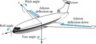
FIGURE Pl.2 Aircraft attitude defined
Expert Solution & Answer
Want to see the full answer?
Check out a sample textbook solution
Students have asked these similar questions
The governor is a mechanically-controlled feedback device which maintains the speed
of an engine within permissible range whenever there is a variation of load. There is
various type of governor in the industry as shown in Q6(a). With the aid of a diagram
of forces acting on the governor at the equilibrium, explain the limitations of a Watt
governor and how these are rectified in the Porter governor.
Figure Q6(a): Various types of governor.
Problem 3:
Crankshaft mechanism is one of the most important mechanical system used to convert translational motion or
reciprocating motion to rotational motion and vice versa. It is widely used in cars' engines and hydraulic pumps.
Your role in car's engine manufacturing company is to analyze the displacement, velocity and acceleration
diagrams for crankshaft planer mechanism to later find the forces of the links to avoid overloading the system.
Your manger asked you the provide detailed analysis of the crankshaft planar mechanism shown in Figure.3.
Part.1:
-140 mm
60 mm
Crank
Connecting Rod
x(t)
V(t)
a(t)
F(t)
(OB
Piston
x(t)
Reference
Figure.3: Crankshaft planar mechanism for a car 'engine.
If the zero-position x=0 at the extreme right as shown in Figure.3, perform the following tasks:
1. Derive a mathematical relation for displacement, velocity and acceleration x(t), v(t) and a(t) of the
piston B.
2. Derive a mathematical relation for force F(t) on the piston B by making use of the…
Task 1):
The quarter-car model of a vehicle suspension and its free body diagram are shown in
Figure 1. In this simplified model, the masses of the wheel, tire, and axle are neglected,
and the mass m represents one-fourth of the vehicle mass. The spring constant k models
the elasticity of both the tire and the suspension spring. The damping constant c models
the shock absorber. The equilibrium position of m when y=0 is x=0. The road surface
displacement y(t) can be derived from the road surface profile and the car's speed.
a) Draw free body diagram (FBD) and derive the equation of motion of m with y(t) as the
input, and obtain the transfer function.
Body
m
1
Suspension
Road
k
Datum level
Figure 1
Dynamic Analysis and Control
If assume:
m=250 kg
k=10000, 30000, 50000 N/m
c=1000, 2000, 3000 N.s/m
b) Plot magnification ratio vs frequency ratio (r=0-4) diagrams for the parameters given
above (you can draw the three curves in one diagram for three different k values and
do the same for the…
Chapter 1 Solutions
CONTROL SYSTEMS ENGINEERING
Ch. 1 - Prob. 1RQCh. 1 - Prob. 2RQCh. 1 - Prob. 3RQCh. 1 - Prob. 4RQCh. 1 - State one condition under which the error signal...Ch. 1 - Prob. 6RQCh. 1 - Name two advantages of having a computer in the...Ch. 1 - Name the three major design criteria for control...Ch. 1 - Prob. 9RQCh. 1 - Physically, what happens to a system that is...
Ch. 1 - Instability is attributable to what pan of the...Ch. 1 - Describe a typical control system analy sis task.Ch. 1 - Describe a typical control system design task.Ch. 1 - Prob. 14RQCh. 1 - Name three approaches to the mathematical modeling...Ch. 1 - Briefly describe each of your answers to Question...Ch. 1 - Prob. 1PCh. 1 - Prob. 2PCh. 1 - An aircraft's attitude varies in roll, pitch, and...Ch. 1 - We can build a control system that will...Ch. 1 - Prob. 5PCh. 1 - During a medical operation an anesthesiologist...Ch. 1 - Prob. 7PCh. 1 - Prob. 8PCh. 1 - The human eye has a biological control system that...Ch. 1 - A Segway ®5 Personal Transporter (PT) (Figure Pl...Ch. 1 - In humans, hormone levels, alertness, and core...Ch. 1 - Tactile feedback is an important component in the...Ch. 1 - Prob. 13PCh. 1 - Moored floating platforms are subject to external...Ch. 1 - In the Case Study of Section 1.4. an antenna...Ch. 1 - Figure Pl.5 shows the topology of a photo-voltaic...Ch. 1 - Prob. 17PCh. 1 - Prob. 18PCh. 1 - Prob. 19PCh. 1 - Prob. 20PCh. 1 - Prob. 21PCh. 1 - Contol of HIV/AIDS. As of 2012. the number of...Ch. 1 - Prob. 23PCh. 1 - Parabolic trough collector. A set of parabolic...
Knowledge Booster


Learn more about
Need a deep-dive on the concept behind this application? Look no further. Learn more about this topic, mechanical-engineering and related others by exploring similar questions and additional content below.Similar questions
- 2. A model for an airplane's pitch loop is shown below. Find the range of K that will keep the system stable. Can the system ever be unstable for positive values of K? Controller Aircraft dynamics Commanded pitch angle + K(s + 1) Pitch angle s + 10 s2 + 0.6s + 9 (s + 4.85) 1 Gyroarrow_forwardFrame the three equations and find the constants of the Freudenstein's equation for the given data. A four-bar mechanism is to be designed in a automotive industry to perform automation of packaging. The given input angles and the required output angles are given below. O, is along 03 is 40° greater than 02 Input angle, 0 02 is 30° greater than 01 positive x axis Pi is 20° lesser than P2 Output angle, O P 2 is same as 03 P3 = 02arrow_forwardHello, I need the correct response and the formula to slave this problem please. I want to found the technic to get the value of h.Thank youarrow_forward
- Learning Goal: To understand how to use the relative position and velocity equations to find the linear and angular velocity of members in an assembly. A piston is driven by a crankshaft as shown. The crank arm (member AB) has a length of ri = 0.50 in and the connecting rod (member BC') has a length of r2 = 3.65 in . The crankshaft rotates in the counterclockwise or positive direction.(Figure 1) y r2 Find the magnitude of the velocity of C, vc, when the piston has moved to the new position 0 = 27.0° and ø = 7.01° The crankshaft (member AB) is still rotating at 220 rpm . Express your answer to three significant figures and include the appropriate units. • View Available Hint(s) Value Units Submitarrow_forwardLearning Goal: To understand how to use the relative position and velocity equations to find the linear and angular velocity of members in an assembly. A piston is driven by a crankshaft as shown. The crank arm (member AB) has a length of r₁=0.55 in and the connecting rod (member BC) has a length of r2 = 4.25 in. The crankshaft rotates in the counterclockwise or positive direction. (Figure 1) Figure C 1₂ @₂ @1 0 B X 1 of 2 Part C - Velocity of C Find the magnitude of the velocity of C, vc, when the piston has moved to the new position = 33.0° and p = 6.23°. The crankshaft (member AB) is still rotating at 300 rpm Express your answer to three significant figures and include the appropriate units. ► View Available Hint(s) vc= 15.5 in S Submit Completed Part D - Rotational Speed of the Crankshaft W1 = Previous Answers The velocity of the piston is vc = 70.0 in/s j the instant when 0 = 33.0° and = 6.23°. Find the rotational speed of the crankshaft (member AB) at this instant. The crankshaft…arrow_forward2. Determine the transfer function from aileron deflection to roll rate in a F-104A aircraft. Assume the airplane is flying at sea level at a speed of 87m/sec. The F104A has the following aerodynamic and geometric data: Mass moment of inertia about the roll axis: I, = 4676kg m? Roll damping: 6079N m/rad/sec Roll moment from aileron control input: 380N m/degarrow_forward
- Q4) In Fig.2, The location of the tool, 77 is not accurately known. Using force control, the robot feels around with the tool tip until it inserts it into the socket (or Goal) at loca- tiongr. Once in this "calibration" configuration (in which (G) and (T) are coincident), the position of the robot, is figured out by reading the joint angle sensors and com- puting the kinematics. Assuming T and T are known, give the transform equation to compute the un- known tool frame,T. 2 Fig.2arrow_forwardWhat are the Lagrange equations of the PR manipulator?arrow_forwardConsider two robot-manipulators:• A SCARA robot with joints displacement range q1,2 = −90◦...90◦ and q3 = 0..10cm and links lengths L1,2=10 cm.• A Cartesian robot with joint displacements’ range q1,2,3 = 0..10 cm.Which statement is correct?1) The Cartesian robot has a larger workspace.2) It is not possible to judge the workspace based on the information provided.3) Both robots have revolute joints.4) The SCARA robot has a larger workspace.arrow_forward
- 4) If the forward function for a control system is given below, and the feed backward is unity. Find the range of (K) that make this system stable: G(s) = 7K S5+254 +353 +5S2 + 2S +8 425arrow_forward1. For the linkage system show, Link 1 moves along the vertical direction via a linear motor. Link 2 and 3,,dependent on the motion of Link 1, will move accordingly. Perform position analysis using Chace Mehod: Draw the loop closure vectors for the problem. (a) (b) Determine the unknowns. (c) Determine which kinematic case it is (d) Determine equations for the unknowns as function of known variables. (e) Assume link 1 is located 3 inches above the x-y coordinates, and link 2 has a length of 5 inches. Determine the numerical values of the two unknowns for this specific configuration. Link 1 X Link 2 Link 3arrow_forwardHelp me with this ASAP. Thank you! Find the Following: 1. Natural angular velocity 2.Damped angular velocity 3. Equation of motion x(t). Assume Initial conditions for displacement and velocity 4. Graph 2 cycles of the vibrating system. You can use third party app for this.arrow_forward
arrow_back_ios
SEE MORE QUESTIONS
arrow_forward_ios
Recommended textbooks for you
 Elements Of ElectromagneticsMechanical EngineeringISBN:9780190698614Author:Sadiku, Matthew N. O.Publisher:Oxford University Press
 Mechanics of Materials (10th Edition)Mechanical EngineeringISBN:9780134319650Author:Russell C. HibbelerPublisher:PEARSON
 Thermodynamics: An Engineering ApproachMechanical EngineeringISBN:9781259822674Author:Yunus A. Cengel Dr., Michael A. BolesPublisher:McGraw-Hill Education
 Control Systems EngineeringMechanical EngineeringISBN:9781118170519Author:Norman S. NisePublisher:WILEY
 Mechanics of Materials (MindTap Course List)Mechanical EngineeringISBN:9781337093347Author:Barry J. Goodno, James M. GerePublisher:Cengage Learning
 Engineering Mechanics: StaticsMechanical EngineeringISBN:9781118807330Author:James L. Meriam, L. G. Kraige, J. N. BoltonPublisher:WILEY
Elements Of Electromagnetics
Mechanical Engineering
ISBN:9780190698614
Author:Sadiku, Matthew N. O.
Publisher:Oxford University Press
Mechanics of Materials (10th Edition)
Mechanical Engineering
ISBN:9780134319650
Author:Russell C. Hibbeler
Publisher:PEARSON
Thermodynamics: An Engineering Approach
Mechanical Engineering
ISBN:9781259822674
Author:Yunus A. Cengel Dr., Michael A. Boles
Publisher:McGraw-Hill Education
Control Systems Engineering
Mechanical Engineering
ISBN:9781118170519
Author:Norman S. Nise
Publisher:WILEY
Mechanics of Materials (MindTap Course List)
Mechanical Engineering
ISBN:9781337093347
Author:Barry J. Goodno, James M. Gere
Publisher:Cengage Learning
Engineering Mechanics: Statics
Mechanical Engineering
ISBN:9781118807330
Author:James L. Meriam, L. G. Kraige, J. N. Bolton
Publisher:WILEY
Dynamics - Lesson 1: Introduction and Constant Acceleration Equations; Author: Jeff Hanson;https://www.youtube.com/watch?v=7aMiZ3b0Ieg;License: Standard YouTube License, CC-BY