
Concept explainers
Videos
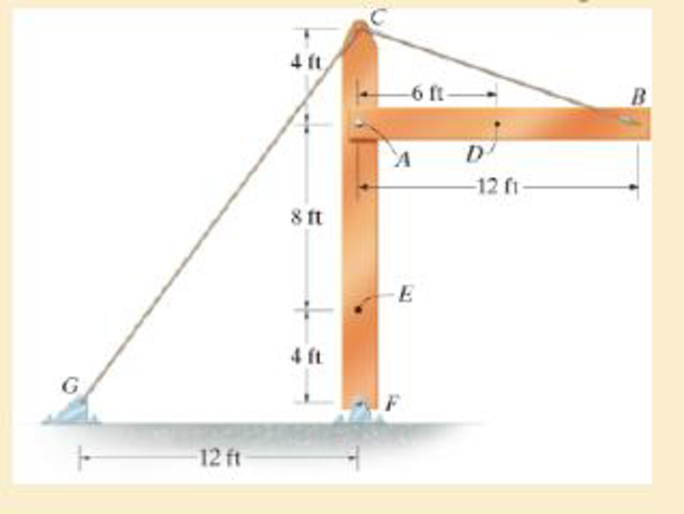
The beam AB is pin supported at A and supported by a cable BC. A separate cable CG is used to hold up the frame. If AB weighs 120 lb/ft and the column FC has a weight of 180 lb/ft, determine the resultant internal loadings acting on cross sections located at points D and E.
Answer to Problem 1.97RP
The resultant internal loadings at cross section at D are
The resultant internal loadings at cross section at E are
Explanation of Solution
Given information:
The beam AB is pin supported at A and supported by a cable BC.
The weight of the beam AB is
The weight of the column FC is
Calculation:
Find the loading at the center of the beam AB
Substitute
Convert the unit from lb to kip.
Sketch the Free Body Diagram of the beam AB shown in Figure 1.
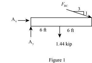
Refer to Figure 1.
Find the angle of cable BC to the horizontal
Find the tension in cable BC as shown below.
Take moment about A is Equal to zero.
Find the support reaction at A as shown below.
Apply the Equations of Equilibrium as shown below.
Summation of forces along horizontal direction is Equal to zero.
Summation of forces along vertical direction is Equal to zero.
Find the loading at the center of the beam AD
Substitute
Convert the unit from lb to kip.
Sketch the Free Body Diagram of the section for point D as shown in Figure 2.
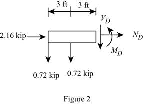
Refer to Figure 2.
Find the internal loadings as shown below.
Apply the Equations of Equilibrium as shown below.
Summation of forces along horizontal direction is Equal to zero.
Summation of forces along vertical direction is Equal to zero.
Take moment about D is Equal to zero.
Hence, the resultant internal loadings at cross section at D are
Find the loading at the center of the column FC
Substitute
Convert the unit from lb to kip.
Sketch the Free Body Diagram of the beam FC shown in Figure 3.
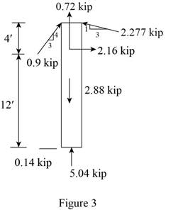
Refer to Figure 3.
Find the angle of cable CG to the horizontal.
Find the tension in cable CG as shown below.
Summation of forces along horizontal direction is Equal to zero.
Find the loading at the center of the column FE
Substitute
Convert the unit from lb to kip.
Sketch the Free Body Diagram of the section for point E as shown in Figure 4.
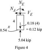
Refer to Figure 4.
Find the internal loadings as shown below.
Apply the Equations of Equilibrium as shown below.
Summation of forces along horizontal direction is Equal to zero.
Summation of forces along vertical direction is Equal to zero.
Take moment about E is Equal to zero.
Therefore, the resultant internal loadings at cross section at E are
Want to see more full solutions like this?
Chapter 1 Solutions
Mechanics of Materials
Additional Engineering Textbook Solutions
Automotive Technology: Principles, Diagnosis, And Service (6th Edition) (halderman Automotive Series)
Thinking Like an Engineer: An Active Learning Approach (4th Edition)
Statics and Mechanics of Materials (5th Edition)
Applied Statics and Strength of Materials (6th Edition)
Thinking Like an Engineer: An Active Learning Approach (3rd Edition)
Engineering Mechanics: Statics & Dynamics (14th Edition)


- Determine the loads acting on pins A and D of the frame shown. On the other hand, if the pin at B can withstand a maximum shear force of 800 lb, determine the maximum distributed load that can be applied to member AB.arrow_forwardA 200-lb man starts at end A of the wooden plank and walks toward end B. If the plank will fail when the maximum bending stress is 6000 psi, find the farthest distance x that the man can walk safely.arrow_forwardThe metal stud punch is subjected to a force of 120 N on the handle. determine the magnitude of the reactive force at the pin A and in the short link BC. Also, determine the resultant internal loadings acting on the cross section at point D.arrow_forward
- The shaft is supported by a smooth thrust bearing at A and a smooth journal bearing at B. Determine the resultant internal loadings acting on the cross-section at C.arrow_forwardThe triangular block below is subjected to the Loads P=1200 lb and 400 lb. If AB=8 in, and BC is 6in., resolve each load into components normal and tangential to AC.arrow_forwardThe beam is supporting a distributed load of w=660 lb/ft. Determine the magnitudes of the resultant internal loadings acting on section b–b through the centroid C on the beam. Show all work and any FBDs that apply.arrow_forward
- The hand crank that is used in a press has the dimensions shown. Determine the resultant internal loadings acting on the cross-section at point A if a vertical force of 50 lb is applied to the handle as shown. Assume thecrank is fixed to the shaft at B.arrow_forwardThe bar supported by a pin at A and a cable at Bcarries a load of 260 N at C. Neglecting the weight of the bar,a.) Determine the normal force 3 m from A.b.) Determine the shear force 3 m from A.c.) Determine the bending moment 3 m from Ad.) Determine the torsion 3 m from Aarrow_forwardThe two timber beams loaded as shown are connected by a roller support at point C and supported by hinge at D and A. Beam AC is supported by steel rod 3m from point A. Determine the vertical displacement at point C. Show all the necessary solution.arrow_forward
- The shaft is supported at its ends by two bearings A and B and is subjected to the forces applied to the pulleys fixed to the shaft. Determine the resultant internal loadings acting on the cross-section at point D. The 400-N forces act in the -z-direction and the 200-N and 80-N forces act in the +y direction. The journal bearings at A and B exert only y and z components of force on the shaft.arrow_forwardThe beam supports the triangular distributed load shown. Determine the resultant internal loadings on the cross section at point C. Assume the reactions at the supports A and B are vertical.arrow_forwardAssume point D is just to the left of the 60-kN force. Take wmax = 55 kN/m. Assume the support reactions at A and B are vertical A) Determine the magnitude of the resultant internal normal force on the cross section at point D. B)Determine the magnitude of the resultant internal shear force on the cross section at point D.arrow_forward
 Elements Of ElectromagneticsMechanical EngineeringISBN:9780190698614Author:Sadiku, Matthew N. O.Publisher:Oxford University Press
 Mechanics of Materials (10th Edition)Mechanical EngineeringISBN:9780134319650Author:Russell C. HibbelerPublisher:PEARSON
 Thermodynamics: An Engineering ApproachMechanical EngineeringISBN:9781259822674Author:Yunus A. Cengel Dr., Michael A. BolesPublisher:McGraw-Hill Education
 Control Systems EngineeringMechanical EngineeringISBN:9781118170519Author:Norman S. NisePublisher:WILEY
 Mechanics of Materials (MindTap Course List)Mechanical EngineeringISBN:9781337093347Author:Barry J. Goodno, James M. GerePublisher:Cengage Learning
 Engineering Mechanics: StaticsMechanical EngineeringISBN:9781118807330Author:James L. Meriam, L. G. Kraige, J. N. BoltonPublisher:WILEY